
Acoustic/electronic drum assembly

a drum and electronic technology, applied in the field of acoustic/electronic drum assembly, musical drums, can solve the problems of lack of dynamic range and variations associated with acoustic drums, limited range of sampled sounds provided by computer modules, and the processing of those sounds, etc., to achieve the effect of preserving much of the sound and tonal characteristics

Inactive Publication Date: 2015-01-13
RTOM CORP CORP
View PDF85 Cites 10 Cited by
  • Summary
  • Abstract
  • Description
  • Claims
  • Application Information

AI Technical Summary

Benefits of technology

[0012]As used herein, a “mesh” membrane of the batter drumhead refers to a permeable membrane, having an open weave with openings through which air can pass, formed as a woven material, a perforated material or the like. The mesh membrane is the antithesis of a solid, substantially solid, acoustic or resonant membrane (the terms used interchangeably and inclusively herein), as used in acoustic drumheads, and sound energy or volume of the output from a mesh membrane can be far less than the sound energy generated by an acoustic membrane. This reduced output from the mesh membrane provides a quiet playing surface and allows the drummer to experience playing on a tensioned surface, virtually the same as that of an acoustic drumhead, with greatly reduced sound energy output.
[0033]Ultimately the acoustic signals from the one or more resonant heads, as well as possibly the mesh batter head, are combined to create a low volume drum sound that is then amplified and played through speakers or headphones and / or manipulated with a DSP without the drawbacks of triggered electrical systems. By using a mesh batter head one can generate a significant amount of tone and stick attack at a greatly reduced volume, approximately 30 or more dB down from an acoustic drum fitted with a solid batter head.

Problems solved by technology

However, the range of sampled sounds provided by the computer module, and the processing of those sounds, are limited in the range of different sounds and tones.
Moreover, the sounds created are manipulated to replicate the sounds of conventional acoustic drums, but lack the dynamic range and variations associated with acoustic drums.

Method used


Image

  • Acoustic/electronic drum assembly
  • Acoustic/electronic drum assembly
  • Acoustic/electronic drum assembly

Examples


Embodiment Construction

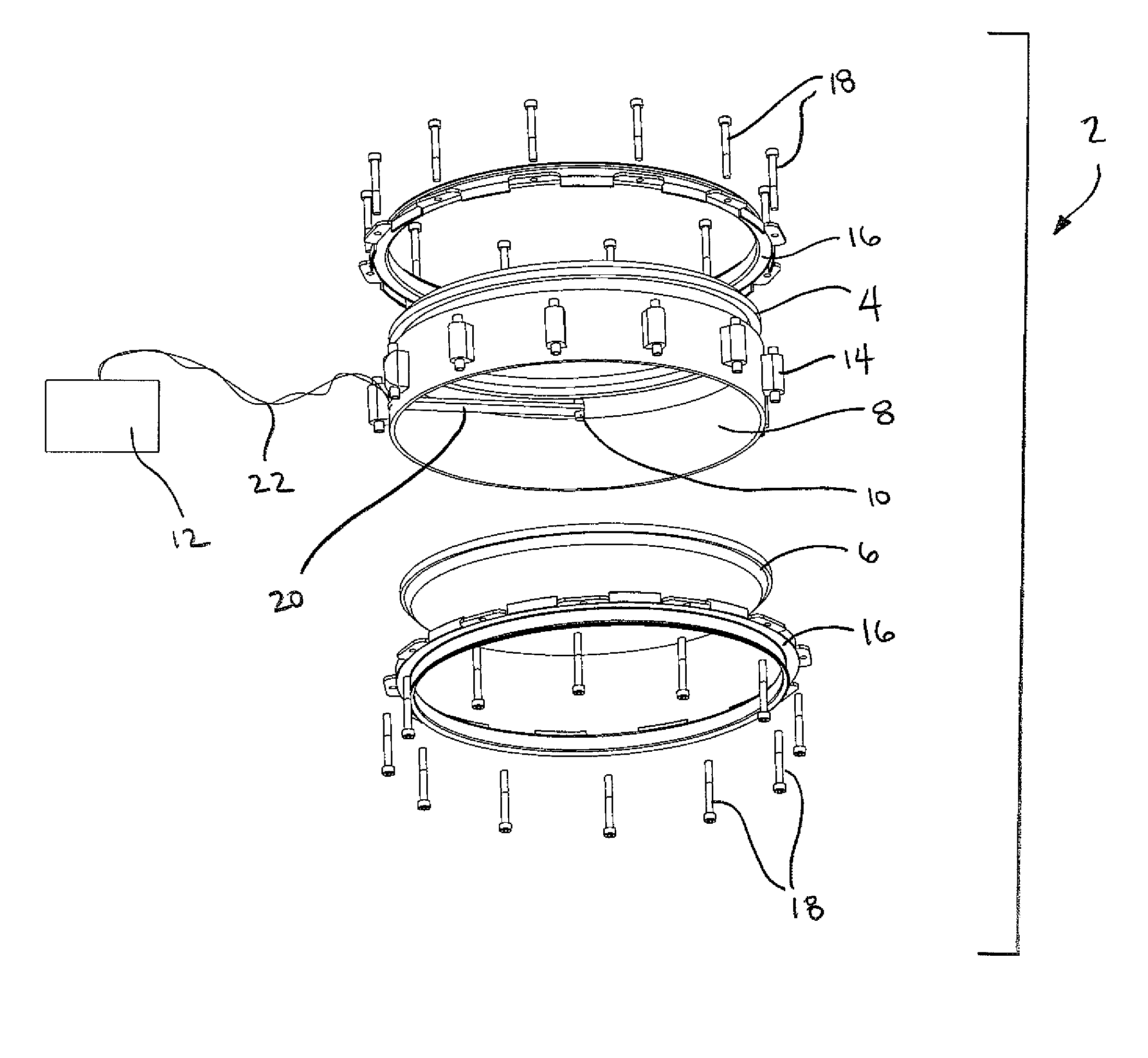
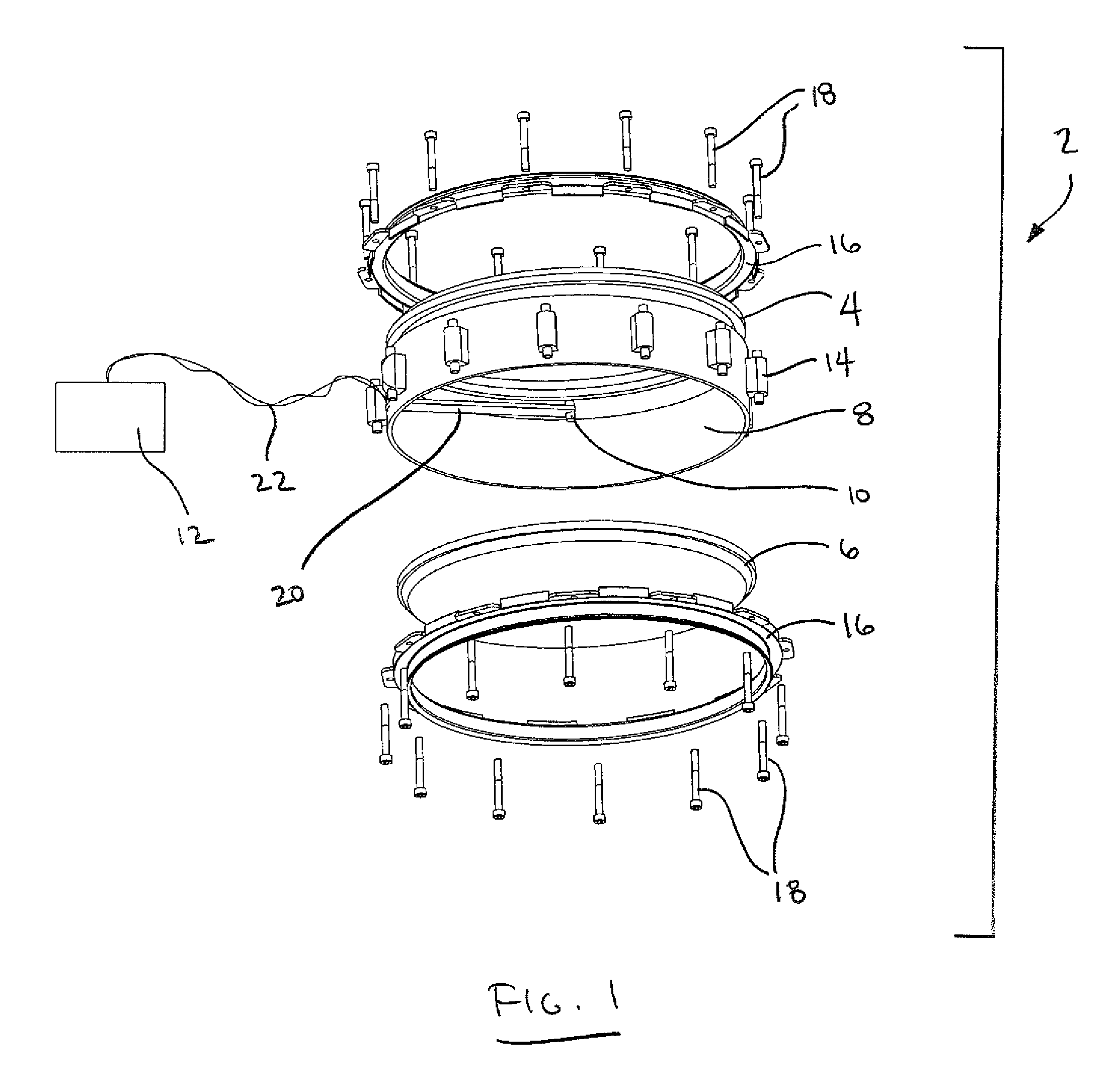
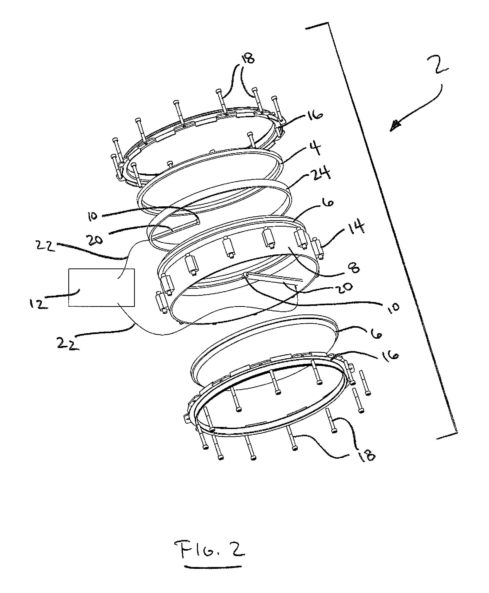
[0038]As shown in the drawings, and particularly FIG. 1, the present invention is directed to a drum 2 comprising a mesh batter drumhead 4 formed of a mesh membrane or open material layer, a resonant drumhead 6 formed of an acoustic membrane, an annular shell member 8 and a pick-up 10 coupled to a digital signal processor (DSP) 12.

[0039]The mesh batter drumhead 4 is manufactured much the same as a standard solid or acoustic drumhead, except with a mesh membrane substituted for the solid membrane of a standard drumhead. More particularly, the peripheral edge of the mesh membrane is fixed into an annular frame or ring using a resin or the like to create the mesh batter drumhead having an annular ring.

[0040]The mesh membrane of the mesh batter drumhead 4 can be fashioned of any suitable material known for making drumheads, but having an open weave. In this regard, a synthetic polymer based material or blend of materials, and preferably a polyester or polyurethane based material, of fro...


PUM


Abstract

An acoustic / electronic drum assembly comprising a mesh batter drumhead comprising a mesh membrane and an annular ring, a resonant drumhead comprising an acoustic membrane and an annular ring, the acoustic membrane capable of creating acoustic sound in response to a force applied to the mesh batter drumhead, an annular shell member for maintaining the mesh batter drumhead in fixed relation to the resonant drumhead, and a pick-up acoustically coupled to at least the resonant drumhead for picking up the acoustic sound and creating an electrical signal.

Description

FIELD OF THE INVENTION[0001]The present invention relates to the field of musical drums and more particularly to the field of musical drums having electronics for pick-up, processing, amplification and user adjustment of acoustic sound and tonal characteristics.BACKGROUND OF THE INVENTION[0002]Conventional acoustic drums are generally comprised of a solid shell and one or two tunable membranes locked into an annular frame, generally referred to as a drumhead, which is tensioned over the shell.[0003]To provide the proper tension to the drumhead, the shell has an arrangement of tensioning lugs attached to it, with threaded tension rods extending from the tensioning lugs. During installation, the drumhead with an annular frame is placed over the shell and a counter hoop, or rim, is placed over the annular frame. The tension rods engage the counter hoop and the tensioning lugs are tightened to stretch the drumhead membrane. By adjusting the torque of the tension rods within the tensioni...

Claims


Application Information

Patent Timeline
Patent Type & Authority Patents(United States)
IPC IPC(8): G10F1/08G10D13/02G10H3/00
CPCG10D13/02G10H3/00G10D13/022G10D13/027G10H3/146G10H2230/275G10D13/14G10D13/20
Inventor ROGERS, THOMAS P.
Owner RTOM CORP CORP
Learn More