Hinge and foldable electronic apparatus therewith

a technology of electronic equipment and hinges, which is applied in the direction of hinges, wing accessories, instruments, etc., can solve the problems of moment output weakening due to abrasion absence, and achieve the effect of avoiding damage to the casing

Active Publication Date: 2015-02-03
WISTRON CORP
View PDF16 Cites 15 Cited by
  • Summary
  • Abstract
  • Description
  • Claims
  • Application Information

AI Technical Summary

Benefits of technology

[0007]Thereby, when the first connection member and the second connection member rotate relatively, the first magnetic part and the second magnetic part also rotate relatively. Because of the magnetic interaction between the first magnetic part and the second magnetic part, the repulsive moment is induced between the first magnetic part and the second magnetic part for resisting the rotation. The repulsive moment is inversely proportional to the distance between the second magnetic part and the first magnetic part; that is, the repulsive moment can be adjusted by adjusting the distance between the first magnetic part and the second magnetic part. Further, the hinge can use a guiding mechanism (for example a guiding slot and a guided rod sliding on the guiding slot) to guide the adjustment part to move in an axial direction of the pivot relative to the first magnetic part during the relative rotation of the first connection member and the second connection member, so that the repulsive moment varies with the relative rotation angle of the first connection member and the second connection member to provide variable repulsive moment output for satisfying different requirements to the hinge. In addition, the production of the repulsive moment is not based on friction force, so the problem in the prior art that the moment output weakens due to abrasion is absent. Therefore, the hinge of the invention can work normally over a quite long time.
[0008]Another objective of the invention is to provide a foldable electronic apparatus, which uses the hinge of the invention to pivotally connect two casings to effectively keep the apparatus at a required unfolded state and avoid damage on the casings due to a sudden folding of the apparatus.
[0010]Similarly, when the first casing and the second casing rotate relatively, the first connection member and the second connection member rotate relatively so that the first magnetic part and the second magnetic part also rotate relatively. Because of the magnetic interaction between the first magnetic part and the second magnetic part, the repulsive moment is induced between the first magnetic part and the second magnetic part for resisting the rotation. Therefore, the repulsive moment can be used to keep the apparatus at a required unfolded state and avoid damage on the casings due to a sudden folding of the apparatus. The repulsive moment is inversely proportional to the distance between the second magnetic part and the first magnetic part; that is, the repulsive moment can be adjusted by adjusting the distance between the first magnetic part and the second magnetic part. In practice, the hinge can use a guiding mechanism (for example a guiding slot and a guided rod sliding on the guiding slot) to guide the adjustment part to move in an axial direction of the pivot relative to the first magnetic part during the relative rotation of the first connection member and the second connection member (for example by unfolding the first casing and the second casing by a user), so that the repulsive moment varies with the relative rotation angle of the first connection member and the second connection member so that during unfolding the foldable electronic apparatus, the hinge provides enough repulsive moment for keeping at the unfolded state without producing excessively large repulsive moment inducing to inconvenience to manipulation of the user.

Problems solved by technology

In addition, the production of the repulsive moment is not based on friction force, so the problem in the prior art that the moment output weakens due to abrasion is absent.

Method used


Image

  • Hinge and foldable electronic apparatus therewith
  • Hinge and foldable electronic apparatus therewith
  • Hinge and foldable electronic apparatus therewith

Examples


Embodiment Construction

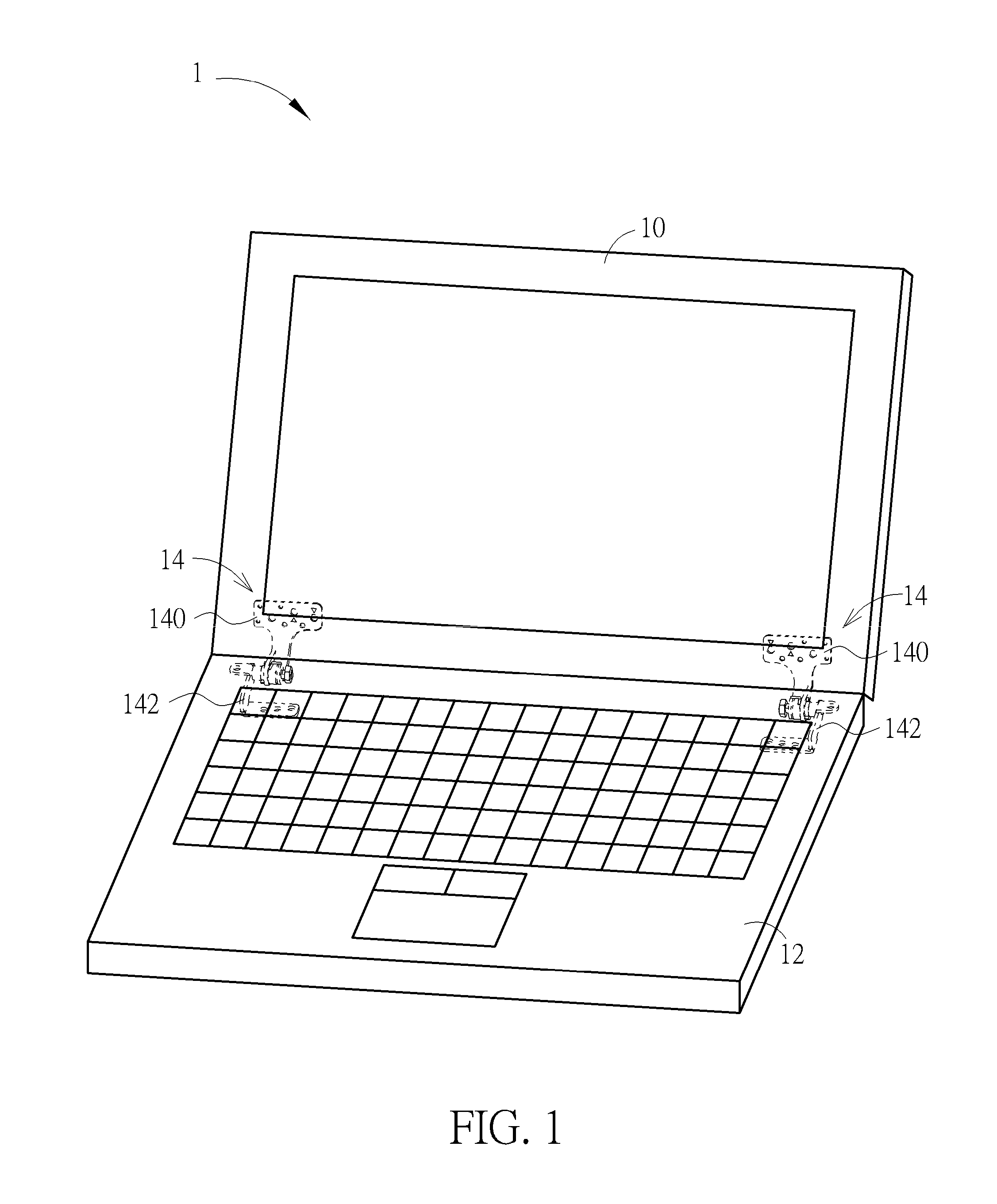
[0027]Please refer to FIG. 1, which is a schematic diagram illustrating a foldable electronic apparatus 1 of a preferred embodiment according to the invention. The foldable electronic apparatus 1 includes a first casing 10, a second casing 12, and two hinges 14. The first casing 10 and the second casing 12 are pivotally connected by these hinges 14 so as to be capable of rotating relatively to be folded or unfolded. In the embodiment, the foldable electronic apparatus 1 is a notebook. The first casing 10 is a monitor, and the second casing 12 is a system host; however, the invention is not limited thereto.

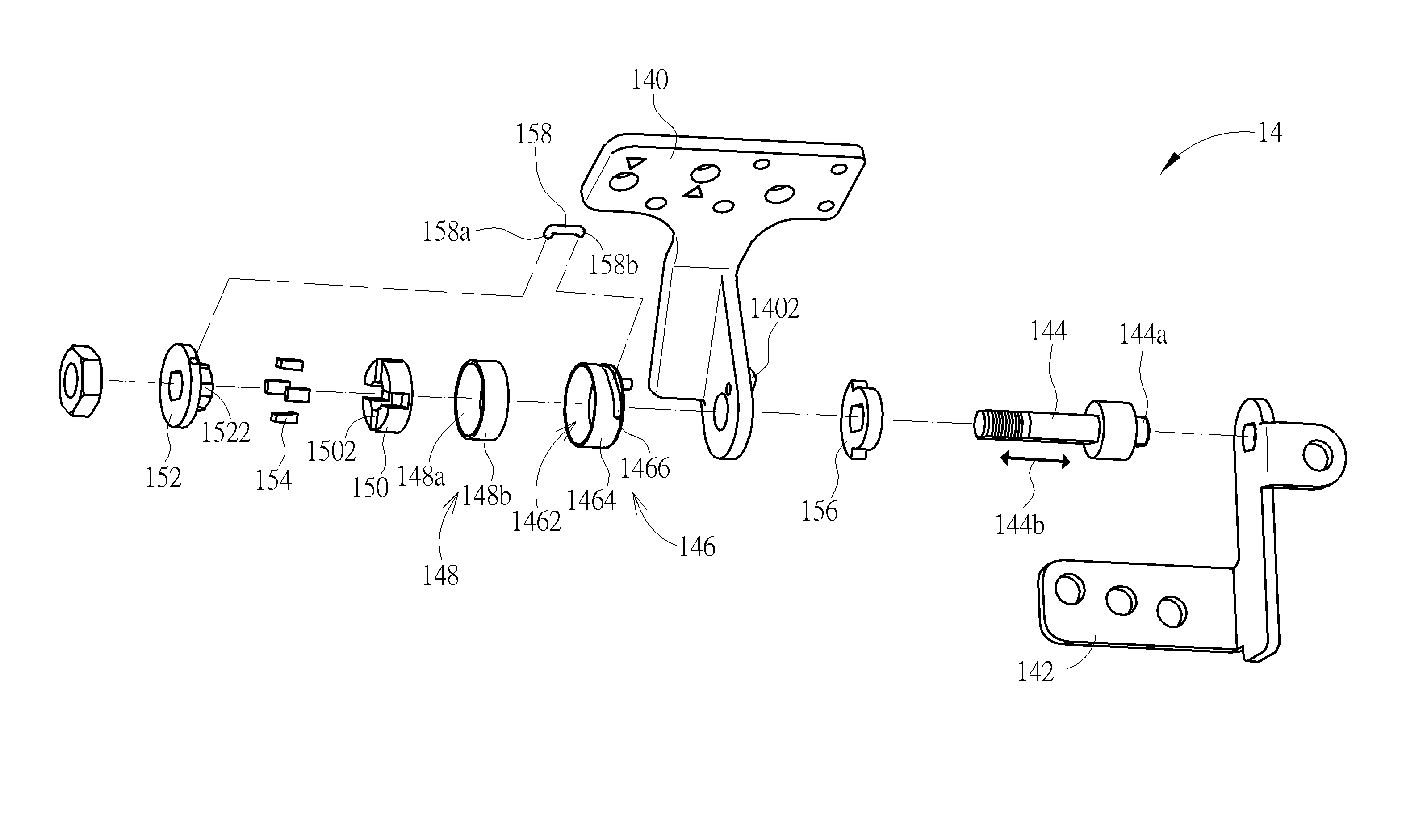
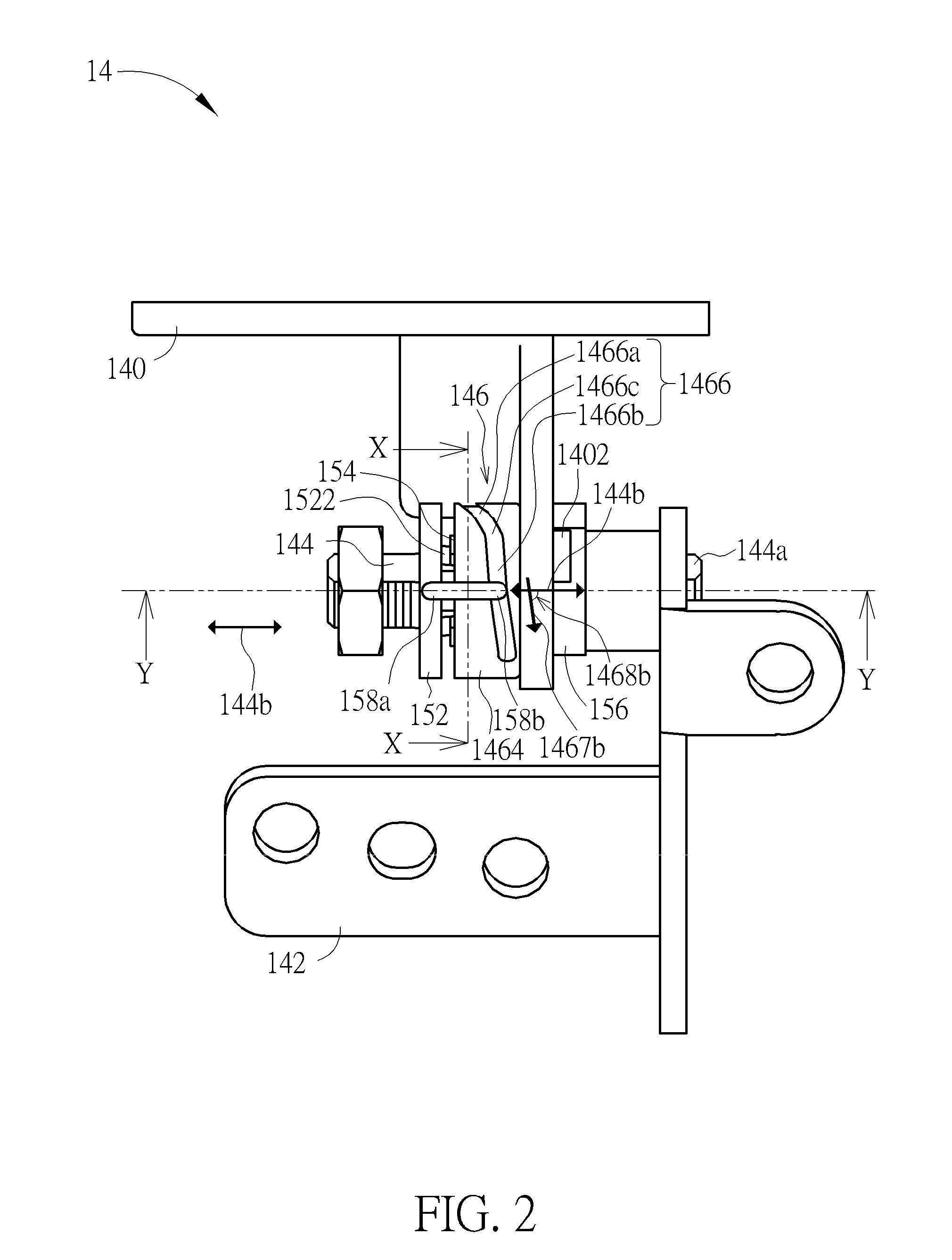
[0028]Please also refer to FIGS. 2 through 4. FIG. 2 is a schematic diagram illustrating the hinge 14. FIG. 3 is an exploded view of the hinge 14. FIG. 4 is a sectional view of the hinge 14 along the line X-X in FIG. 2. The hinge 14 includes a first connection member 140, a second connection member 142, a pivot 144, a socket 146, a first magnetic part 148, a guiding part 150, an ad...


PUM


Abstract

A hinge includes a pivot, two connection members pivotally connected by the pivot, a first magnetic part connected to one of the connection members, a second magnetic part moveably disposed relative to the first magnetic part and kinetically connected to the other one of the connection members, and an adjustment part kinetically connected to the other connection member and urging against the adjustment part. The magnetic moment of the second magnetic part is opposite to that of the first magnetic part. When the two connection members rotate relatively, the other connection member drives the adjustment part and the second magnetic part to rotate relative to the first magnetic part, so as to produce a repulsive moment resisting the rotation and varies with the rotation. A foldable electronic apparatus has the hinge.

Description

BACKGROUND OF THE INVENTION[0001]1. Field of the Invention[0002]The invention relates to a hinge and a foldable electronic apparatus, and especially relates to a hinge providing moment produced by magnetic interaction and a foldable electronic apparatus having the hinge.[0003]2. Description of the Prior Art[0004]Hinges used in conventional notebooks or foldable electronic products need to provide pivotal members and produce an enough moment for keeping the apparatus at a required unfolded state and avoiding damage on components of the apparatus due to sudden folding. Such hinge produces the moment usually produced by friction force when fixing supports of the hinge rotate relatively. In practice, the hinge provides required friction force by use of deformation of several stacked spring washers so as to produce the moment. In such configuration, in principle, once the hinge is assembled completely, the moment provided by the hinge is fixed. If an adjustment of the moment is required,...

Claims


Application Information

Patent Timeline
Patent Type & Authority Patents(United States)
IPC IPC(8): E05D11/10E05D7/00G06F1/16
CPCE05D7/00G06F1/1681
Inventor CHEN, YUAN-TAITSAI, SHAO-HUAICHU, KAI-YUTSAI, YU-HAN
Owner WISTRON CORP
Why Eureka
Try Eureka