Steering system

a steering system and steering force technology, applied in the direction of fastening means, rod connections, vehicle components, etc., can solve the problems of increasing components and assembly costs, and reducing the force required for maintaining the locked condition. , to achieve the effect of sufficient lock maintaining force and low cos

Inactive Publication Date: 2015-02-03
JTEKT CORP
View PDF14 Cites 10 Cited by
  • Summary
  • Abstract
  • Description
  • Claims
  • Application Information

AI Technical Summary

Benefits of technology

[0008]An object of the invention is to provide, at a low cost, a steering system in which a sufficient lock maintaining force is ensured, in spite of variation in dimensional accuracy.
[0010]According to the above-described aspect, at the time of locking by the lock mechanism, the first cam that is rotated together with the lock shaft generates a pressing force for pushing up the inner tube in the upward tilt direction. Further, at the time of locking by the lock mechanism, the abutting portion of the urging member applies a pressing reaction force in the upward tilt direction, to the second cam. The pressing reaction force serves as a force for pushing up the first cam in the upward tilt direction, through the second cam and the lock shaft. This pressing reaction force is superposed on the pressing force with which the first cam itself pushes up the inner tube. Thus, even if there is variation in dimension accuracy among individual components, it is possible to ensure a sufficient lock maintaining force for the inner tube. Further, since the urging force of the urging member that is originally provided for supporting the weight of the steering column at the time of unlocking is applied to the second cam so as to enhance the force for maintaining the locked condition, the structure of the steering system can be simplified and a manufacturing cost can be reduced.

Problems solved by technology

However, there is a possibility that a force for maintaining the locked condition may be weakened at the time of locking, due to variation in dimensional accuracy among individual components.
As a result, there is a possibility that a required push-up force may not be obtained.
In this case, however, a component cost and an assembly cost are increased, and as a result, a manufacturing cost is increased.

Method used


Image

  • Steering system
  • Steering system
  • Steering system

Examples


Embodiment Construction

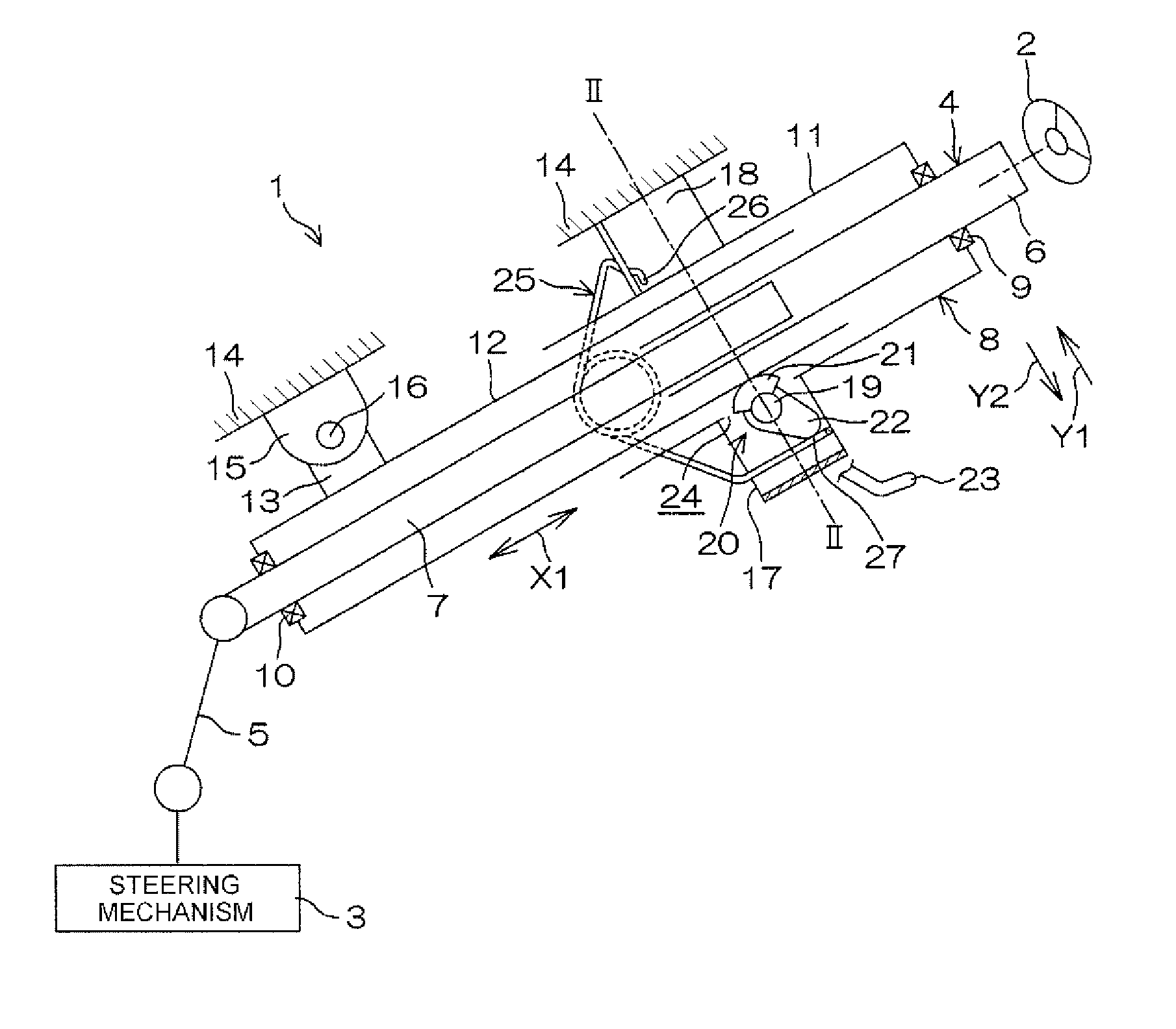
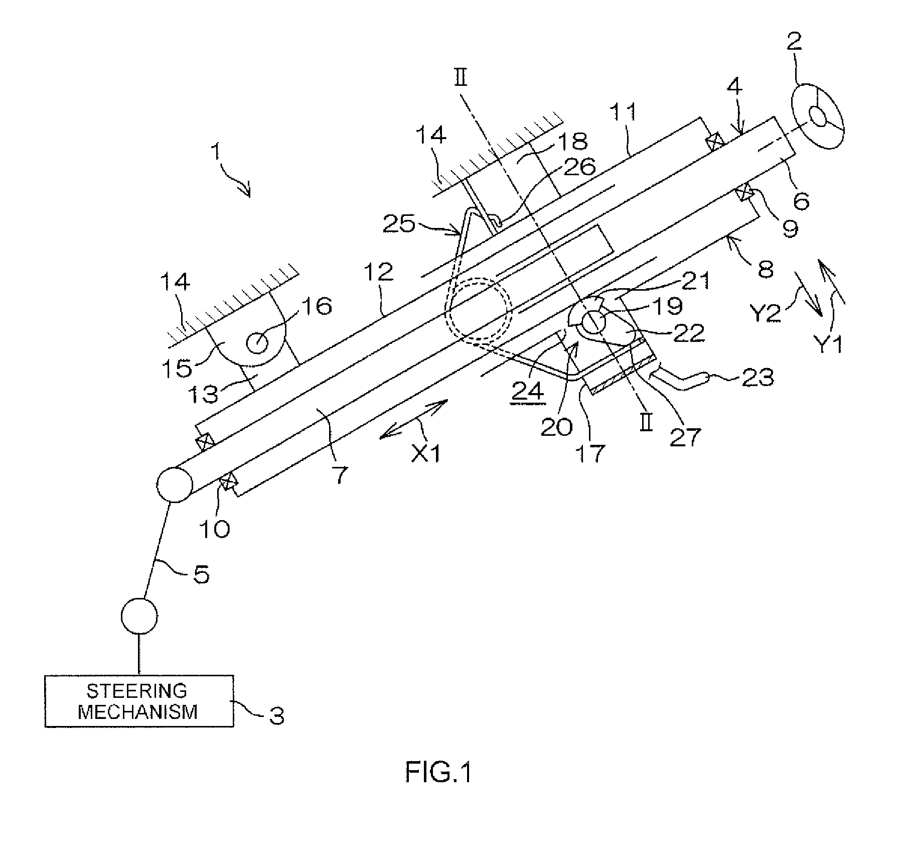
[0019]An embodiment of the present invention will be hereinafter specifically described with reference to the accompanying drawings. Referring to FIG. 1, a steering system 1 includes a steering member 2 such as a steering wheel, and a steering mechanism 3 that steers steered wheels (not shown) in accordance with a steering operation of the steering member 2. For example, a rack and pinion mechanism is used as the steering mechanism 3.

[0020]The steering member 2 is mechanically connected to the steering mechanism 3 through a steering shaft 4, an intermediate shaft 5 and the like. The rotation of the steering member 2 is transmitted to the steering mechanism 3 through the steering shaft 4 and the intermediate shaft 5 and the like. The rotation transmitted to the steering mechanism 3 is converted to axial movement of a rack shaft (not shown). Thus, the steered wheels are steered.

[0021]The steering shaft 4 includes a tubular upper shaft 6 and a tubular lower shaft 7 that are fitted to e...


PUM


Abstract

In a steering system including a lock mechanism, at a time of locking, a first cam that is rotated together with a lock shaft generates a pressing force for pushing up an inner tube in an upward tilt direction. A second cam that is rotated together with the lock shaft presses an abutting portion of an urging member in a downward tilt direction. The abutting portion of the urging member applies a pressing reaction force in the upward tilt direction, to the second cam. The pressing reaction force serves as a force for pushing up the first cam in the upward tilt direction, through the second cam and the lock shaft.

Description

INCORPORATION BY REFERENCE[0001]The disclosure of Japanese Patent Application No. 2012-260174 filed on Nov. 28, 2012 including the specification, drawings and abstract, is incorporated herein by reference in its entirety.BACKGROUND OF THE INVENTION[0002]1. Field of the Invention[0003]The invention relates to a steering system.[0004]2. Description of Related Art[0005]There has been proposed a steering system including a telescopic mechanism constituted by an outer tube and an inner tube that are fitted to each other so as to be slidable relative to each other, wherein the steering system has a telescopic lock function of restricting relative slide movement in the telescopic mechanism, and wherein a single eccentric cam, which is rotated together with a lock shaft in accordance with the operation of an operation lever, presses an outer periphery of the inner tube through an opening formed in the outer tube so as to achieve telescopic lock. For example, refer to Japanese Patent Applica...

Claims


Application Information

Patent Timeline
Patent Type & Authority Patents(United States)
IPC IPC(8): B62D1/184B62D1/187F16B7/14
CPCB62D1/184F16B7/1427B62D1/187
Inventor KAKISHITA, HIDEYUKI
Owner JTEKT CORP
Why Eureka
Try Eureka