Adjustable abrasive sharpener

a technology of abrasives and adjustable angles, applied in the field of sharpeners, can solve the problems that the varying set angles may not match the standard or santoku angle of prior fixed angle sharpeners

Active Publication Date: 2015-02-03
SMITHS CONSUMER PROD
View PDF24 Cites 21 Cited by
  • Summary
  • Abstract
  • Description
  • Claims
  • Application Information

AI Technical Summary

Benefits of technology

[0004]It is therefore an objective of the invention to provide an improved abrasive knife sharpener having adjustable abrasive elements to selectively vary the sharpening angle of a blade. The sharpener includes a pair of pivotally mounted abrasive elements forming a sharpening slot whereby the abrasive elements can selectively be moved toward and away from each other to vary their orientation and sharpening angle. Such adjustability is achieved by a rotary adjustment mechanism for ease of use and significant control of the angle between a respective pair of abrasive elements. By varying the angle between the abrasive elements the user may select a sharpening angle that more closely matches the prescribed manufacture specifications.

Problems solved by technology

These varying set angles may not match the standard or santoku angle of prior fixed angle sharpeners.

Method used


Image

  • Adjustable abrasive sharpener
  • Adjustable abrasive sharpener
  • Adjustable abrasive sharpener

Examples


Embodiment Construction

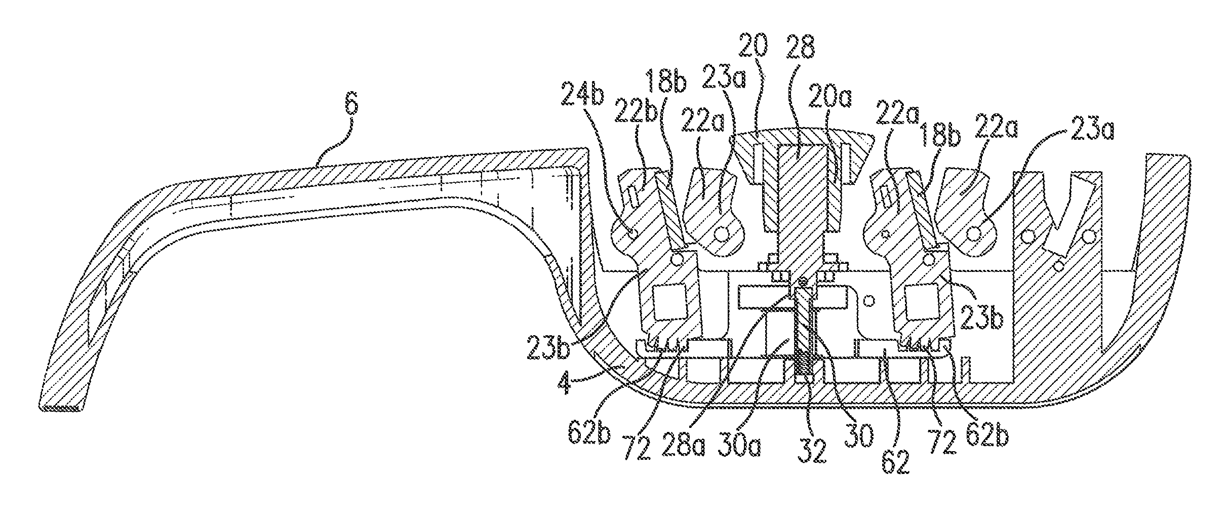
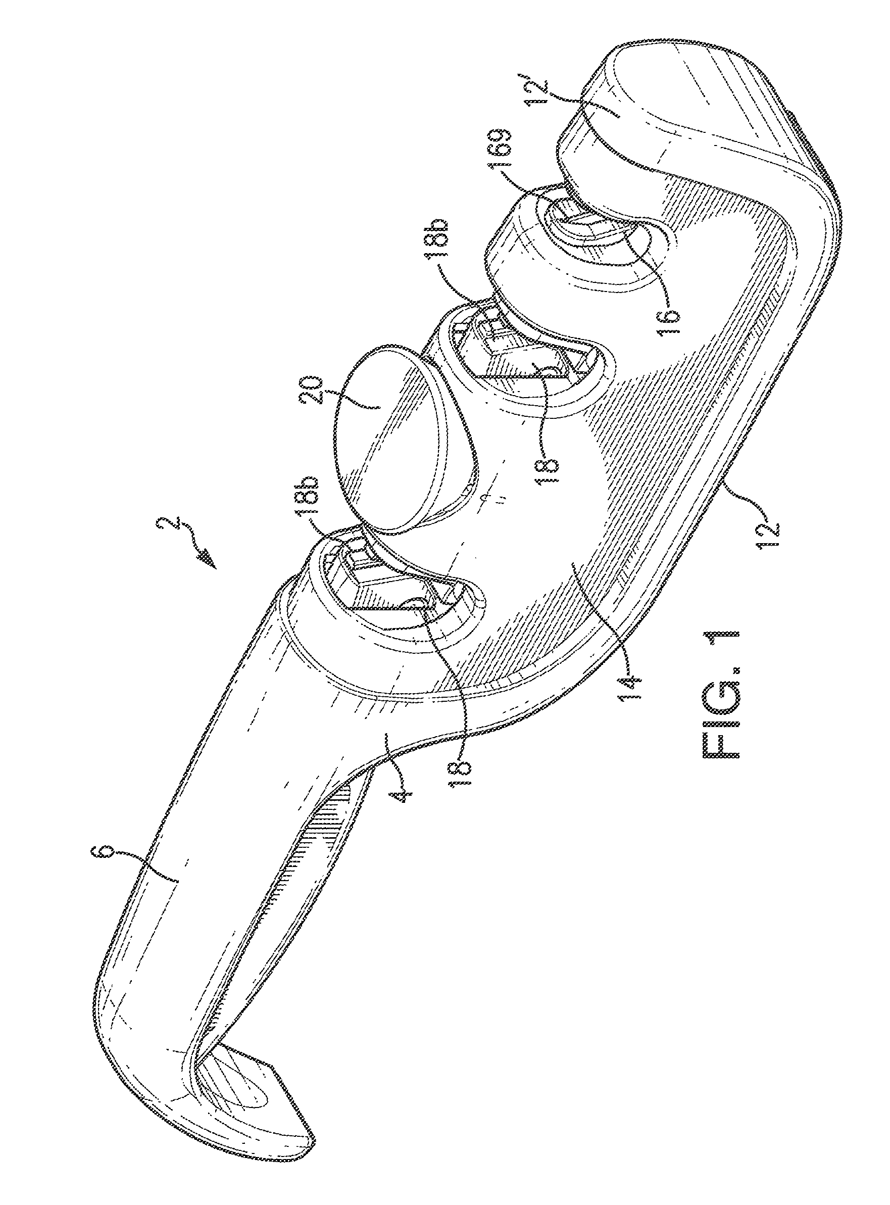
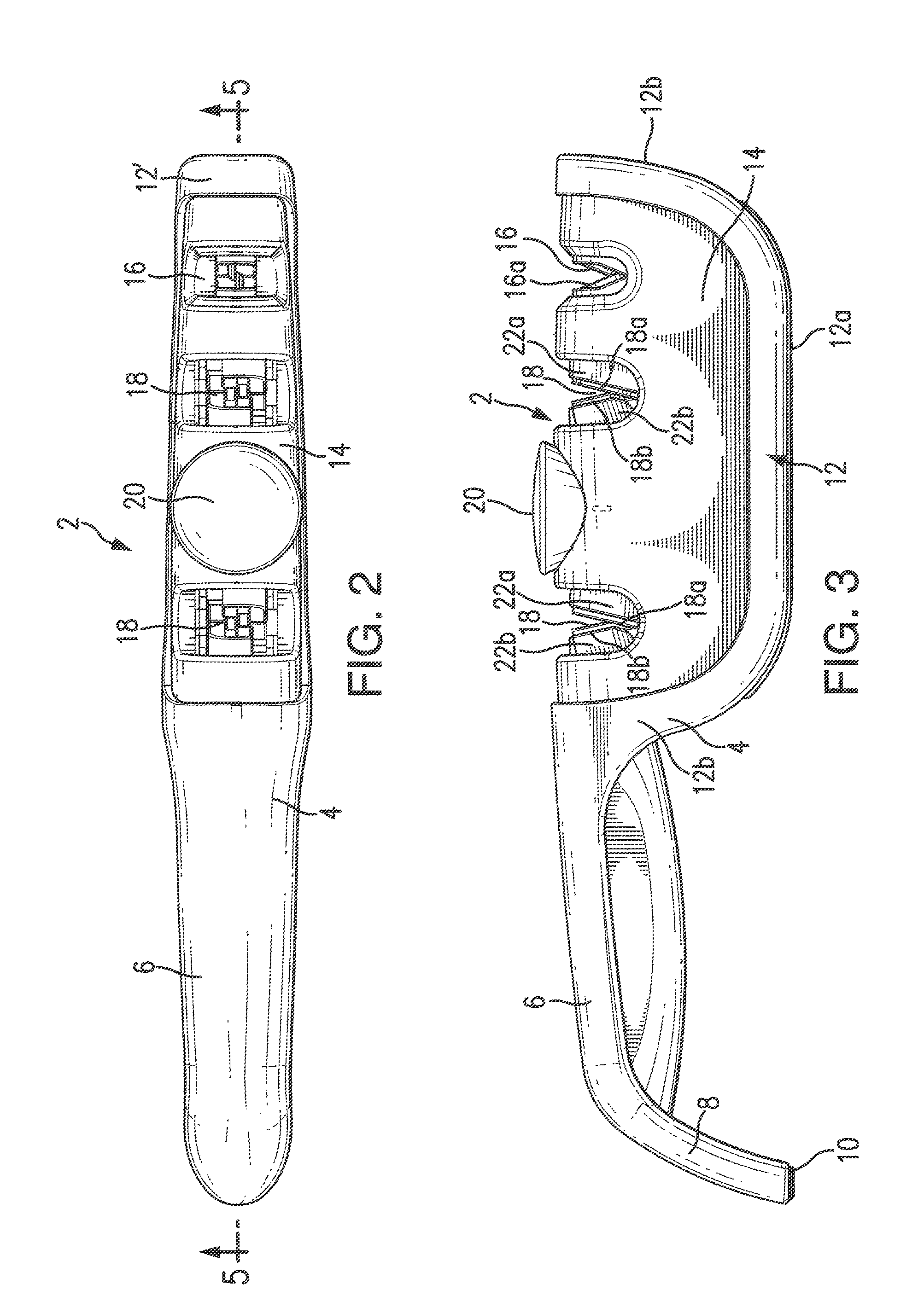
[0018]Referring now to FIGS. 1-13, there is illustrated the adjustable abrasive sharpener of the invention for sharpening knife blades and the like, generally designated by reference numeral 2. Although the sharpener 2 discloses a manual adjustment of the sharpening angle, it is within the scope of the invention to employ other techniques employing the invention, such as an electro-mechanical mechanism (not shown) and the like. As best seen in FIGS. 1-3, the abrasive sharpener 2 includes an elongated frame 4 forming a handle portion 6 at one end. The end 8 of handle 6 curves downward and includes a flat bottom surface 10 which serves as a support area during sharpening. The frame 4 further includes upwardly opening U-shaped section 12 forming a bottom support surface 12a and a curve upward extending portion 12b (FIGS. 3). A housing 14 is positioned within the U-sharped section 12. A sharpening slot 16 having abrasive elements 16a which are oriented to each other at a generally fixed...


PUM

PropertyMeasurementUnit
sharpening angleaaaaaaaaaa
axis of rotationaaaaaaaaaa
rotationaaaaaaaaaa

Abstract

An adjustable manual abrasive sharpener having a pair of sharpening slots formed in a frame with opposing abrasive arms being pivotally mounted in each of the sharpening slots. A rod is mounted on the frame for rotatable motion and for linear motion long its axis of rotation from a position at which the rod is locked against rotation to a depressed position whereby the rod may be rotated. The bottom end portion of the rod includes a pinion gear which engages a pair of gear racks which are mounted for movement laterally relative to the axis of rotation of the rod. The pair of gear racks respectively engage slots formed on the bottom of the abrasive arms in each sharpening slot. Rotation of the rod causes movement of the gear racks to adjust each pair of abrasive arms with respect to each other to vary the sharpening angle of the abrasive elements.

Description

BACKGROUND OF THE INVENTION[0001]This application claims priority to provisional application Ser. No. 61 / 632,038 filed Jan. 17, 2012.FIELD OF THE INVENTION[0002]This invention relates to sharpening knives and the like, and more particularly, to an improved adjustable abrasive sharpener.SUMMARY OF THE PRIOR ART[0003]In the prior art numerous abrasive sharpeners for knives and the like exist having fixed abrasive elements forming a V-shaped sharpening slot. Such known fixed abrasive elements are oriented at a fixed angle to sharpen a blade at an angle as desired for a range of different knife types. Most sharpeners are set at either a standard angle and / or an Asian angle that is preset and static. All manufacturers use blades that produce set knife angles that may vary from knife style to another. These varying set angles may not match the standard or santoku angle of prior fixed angle sharpeners. Accordingly, it is desirable in the prior art to provide an adjustable V-shaped sharpene...

Claims


Application Information

Patent Timeline
Patent Type & Authority Patents(United States)
IPC IPC(8): B24B19/00B24D15/08
CPCB24D15/082Y10S451/918B24D15/081
Inventor SMITH, RICHARD S.CHALFANT, LOUIS
Owner SMITHS CONSUMER PROD
Why Eureka
Try Eureka