
Image data placement method for a time multiplexed autostereoscopic display

a time multiplexed, autostereoscopic display technology, applied in optics, instruments, electrical equipment, etc., can solve problems such as horizontal resolution loss

Inactive Publication Date: 2015-02-03
DIMENSION TECH
View PDF12 Cites 17 Cited by
  • Summary
  • Abstract
  • Description
  • Claims
  • Application Information

AI Technical Summary

Benefits of technology

[0011]The use of time multiplexing provides flexibility in the way in which data can be placed on the LCD in order to control how resolution of the image is distributed between the horizontal and vertical directions. Such control is beneficial since resolution loss is usually less noticeable in the vertical direction, but loss in the horizontal direction may be preferable in some images. Such control also allows tradeoffs between the number of perspective views being displayed and the resolution of the individual views.

Problems solved by technology

There is also resolution loss in the horizontal direction, since a person's eye sees only 1 / N pixel element diagonals.

Method used


Image

  • Image data placement method for a time multiplexed autostereoscopic display
  • Image data placement method for a time multiplexed autostereoscopic display
  • Image data placement method for a time multiplexed autostereoscopic display

Examples


Embodiment Construction

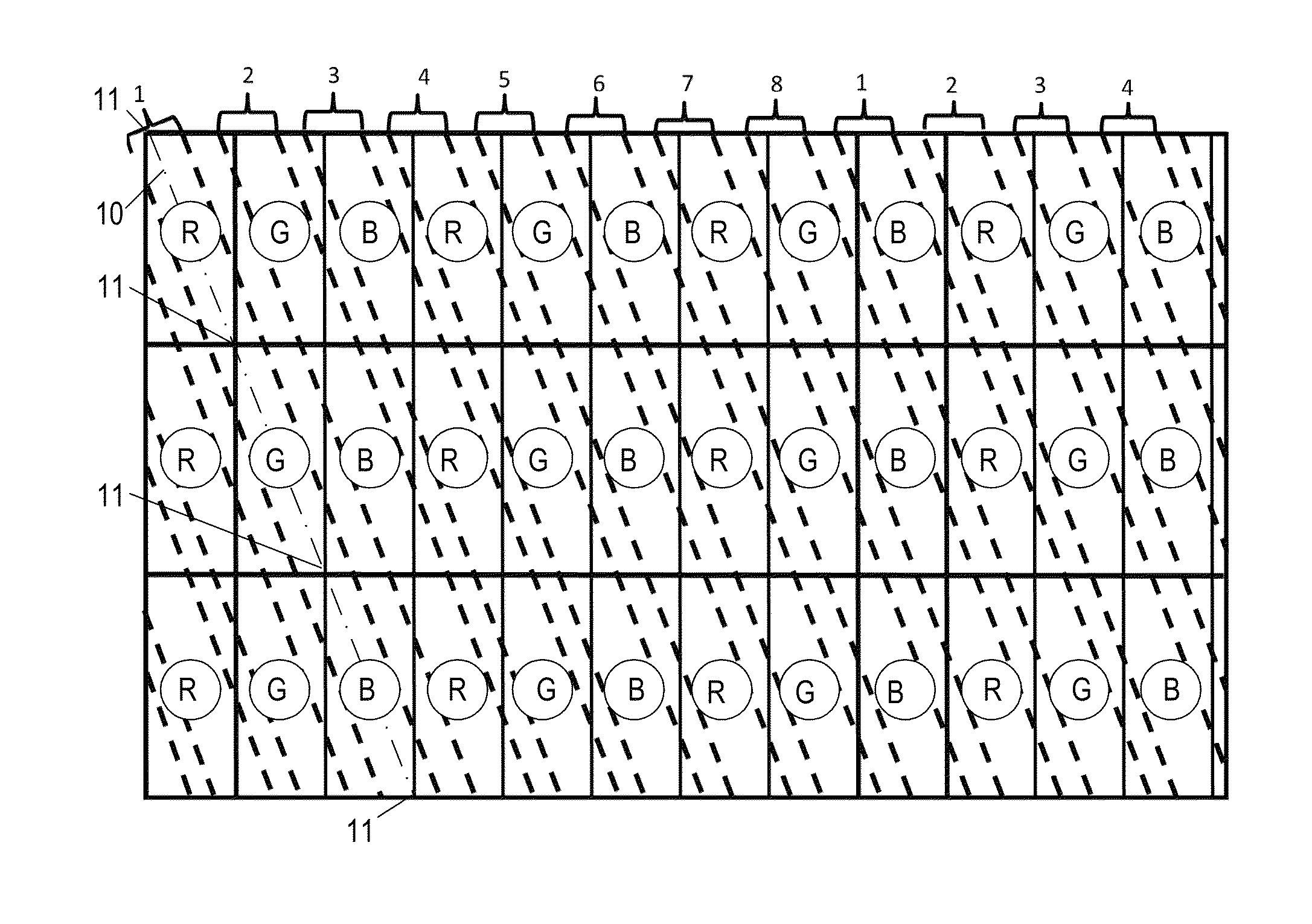
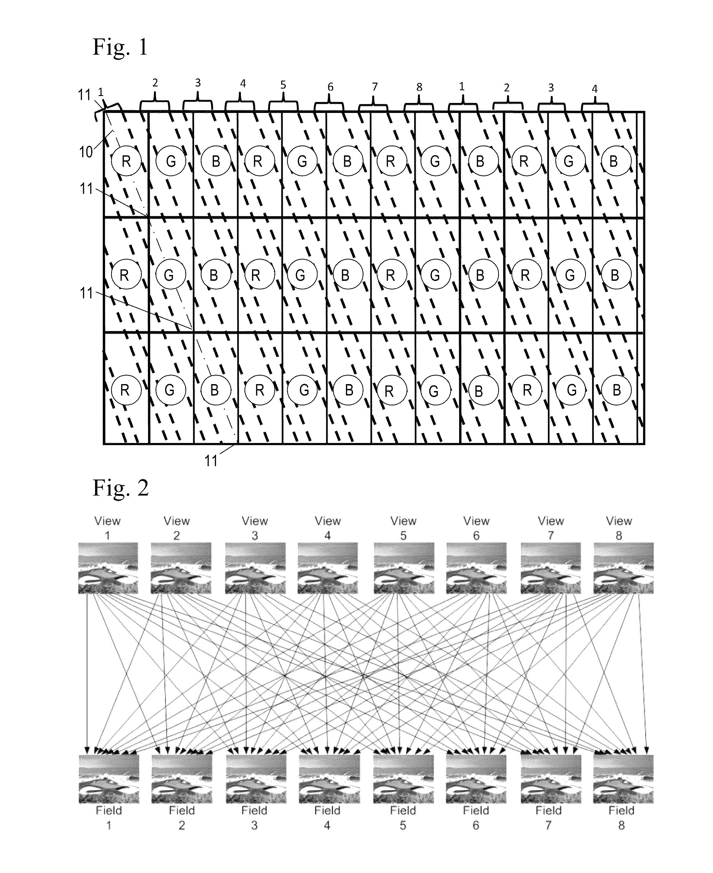
[0025]The co-pending parent application to this continuation-in-part, published as U.S. 2010 / 0118218, describes an autostereoscopic display whereby slanted lines of light are flashed in rapid succession behind a transmissive display, which is generally a liquid crystal display panel (LCD), while the LCD displays a series of images in succession, with one image being displayed during each flash. Typically the light sources used to create each set of lines have several independently controlled sections, which are used to cause different sections of each line to turn on and off in succession, in order to follow the scan of the LCD from top to bottom, as is explained in U.S. Pat. No. 5,410,345 and the aforementioned parent application 2010.0118218.

[0026]The LCD has a resolution of M by N pixels. Each pixel on an LCD display is typically made up of three parts, called elements—a red element, a green element, and a blue element—arranged in a horizontal row within each pixel. This is illus...


PUM

PropertyMeasurementUnit
depthaaaaaaaaaa
depthaaaaaaaaaa
depthaaaaaaaaaa

Abstract

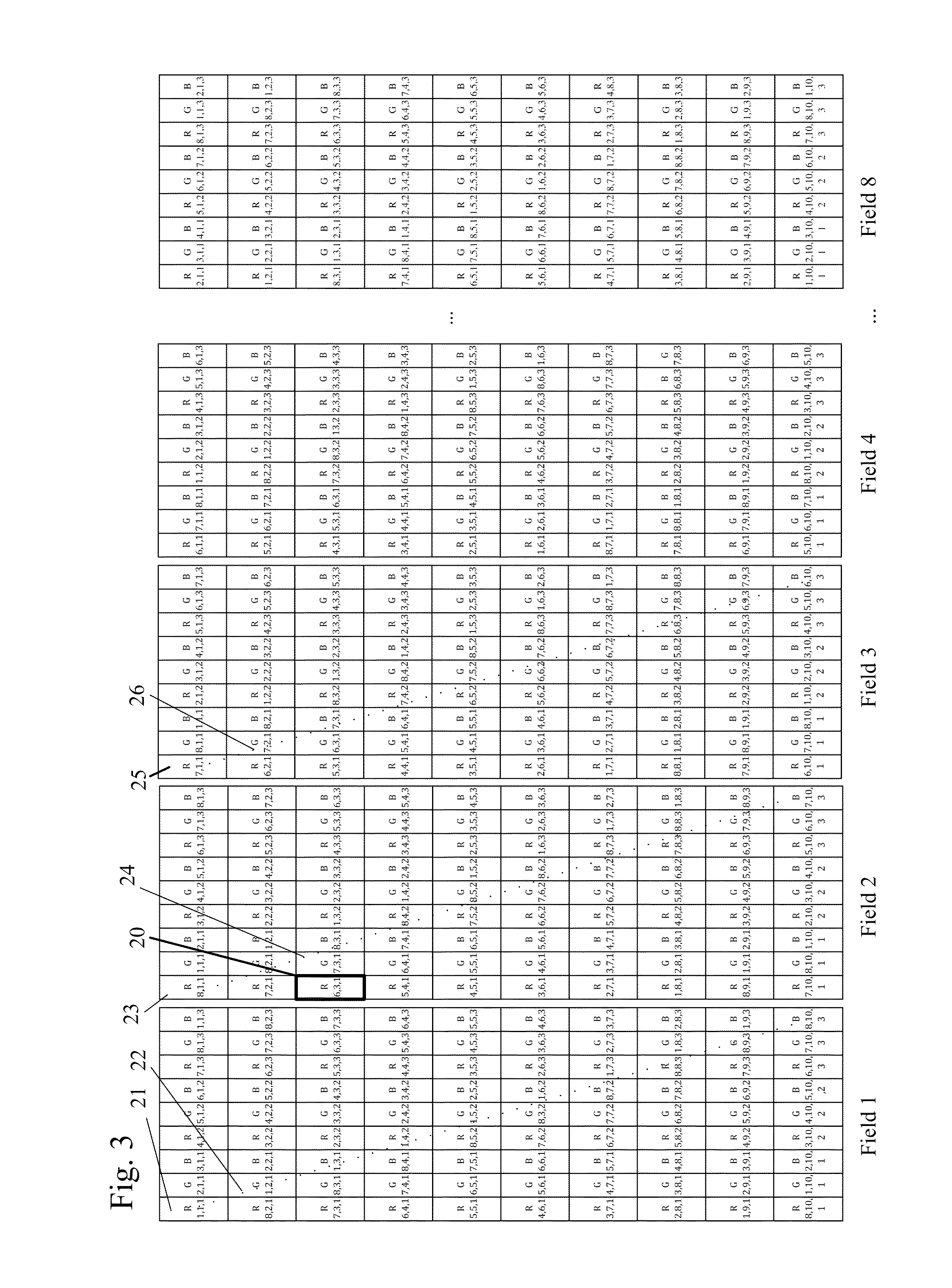
An autostereoscopic display in which image data, in the form of grey level information for red, green, and blue components of pixels in multiple images representing multiple perspective views of a scene, are recombined into a second set of images generally consisting of parts of all the original multiple perspective images, arranged within the second set of images in such a way that a 3D image is seen when the second set of images are displayed in sequence.

Description

REFERENCE TO RELATED APPLICATIONS[0001]This is a continuation-in-part patent application of co-pending application Ser. No. 12 / 613,946, filed Nov. 6, 2009, entitled “Backlighting System for a 2D / 3D Autostereoscopic Multiview Display”, which claimed benefit under 35 USC §119(e) of provisional application No. 60 / 112,424, filed Nov. 7, 2008, entitled “BACKLIGHTING SYSTEM FOR A 2D / 3D AUTOSTEREOSCOPIC MULTIVIEW DISPLAY”. The aforementioned application(s) are hereby incorporated herein by reference.FIELD OF THE INVENTION[0002]The invention pertains to the field of stereoscopic displays. More particularly, the invention pertains to the creation and display of high resolution 3D images that can be seen without 3D glasses.DESCRIPTION OF RELATED ART[0003]U.S. Pat. No. 5,410,345, assigned to Dimension Technologies, Inc. (DTI), describes a method of creating high resolution 3D images by means of multiple sets of flashing vertical light lines placed behind and parallel to the pixel columns of a ...

Claims


Application Information

Patent Timeline
Patent Type & Authority Patents(United States)
IPC IPC(8): G02F1/1335G02B30/31G09G3/00G09G3/34G09G3/36H04N13/00H04N13/04
CPCG02B27/2214G09G3/003G09G3/3426H04N13/0029H04N13/0411H04N13/0413H04N13/0415H04N13/0418H04N13/0422G09G3/3611G09G2300/023G09G2310/0237G09G2310/024G09G2320/068G09G2354/00H04N13/139H04N13/312H04N13/315H04N13/317H04N13/32H04N13/324G02B30/31G02B30/27
Inventor EICHENLAUB, JESSE B.
Owner DIMENSION TECH
Learn More