
Modular raceway with base and integral divider

a module and raceway technology, applied in the direction of connection, contact member material, building components, etc., can solve the problems of not being able or practicable to run electrical cabling (such as high voltage power lines and low voltage data lines) through the building's walls, time-consuming for installers, and difficult to adjust or compensate for variations in spacing

Active Publication Date: 2008-11-20
THE WIREMOLD CO
View PDF7 Cites 11 Cited by
  • Summary
  • Abstract
  • Description
  • Claims
  • Application Information

AI Technical Summary

Benefits of technology

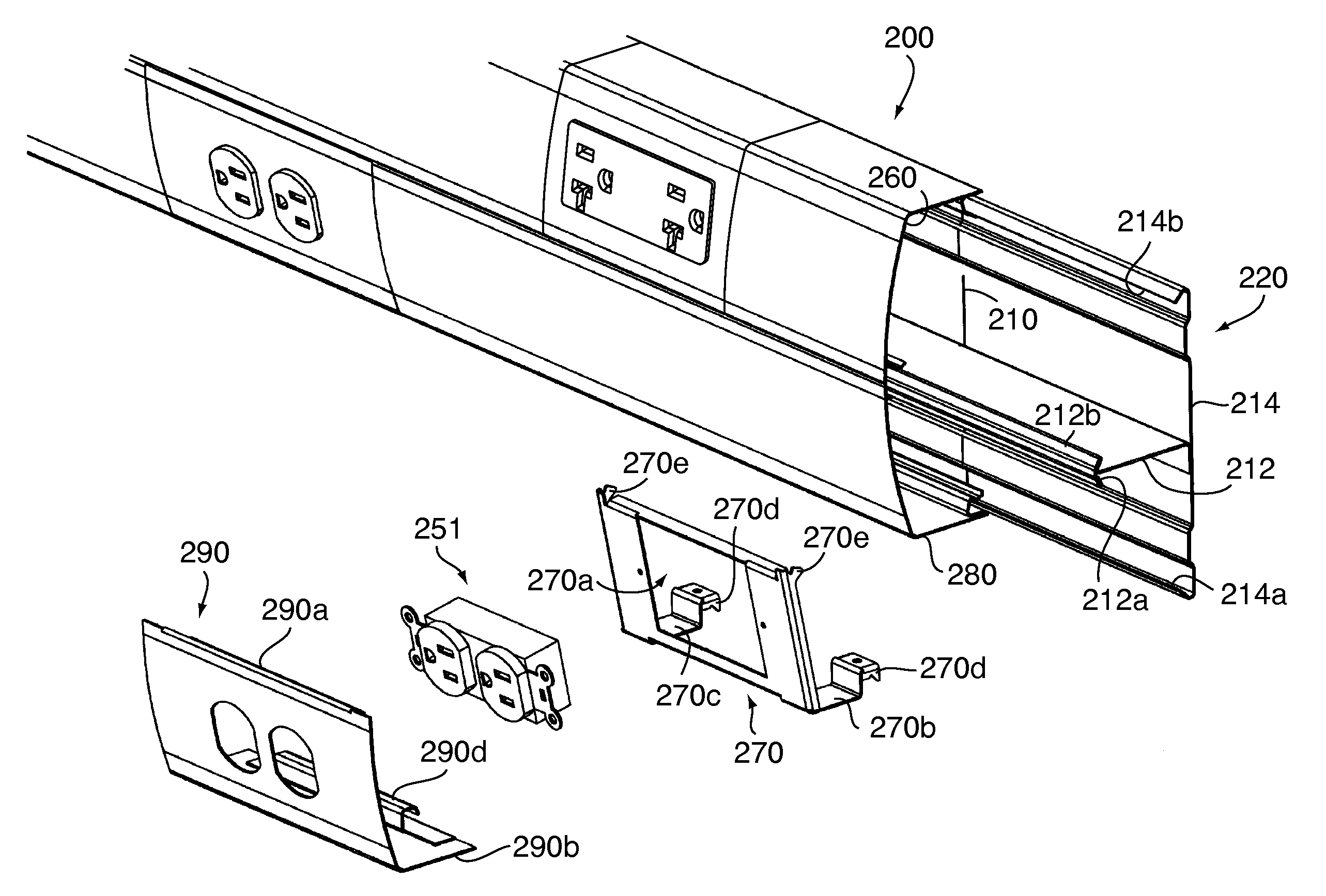
[0007]In another embodiment, the raceway base component is T-shaped. Separate raceway covers are provided for each of the two wireways defined in part by the T-shaped base component. The cover components are generally L-shape in cross section and have end portions designed to mate with the forward or leading edge of the integrally formed divider defined in the base, and to mate as well with the longitudinally extending marginal upper and lower edges of the base. Upper and lower cover components are mounted to the base, and offer flexibility in the placement of power and data / communication outlet devices in one or the other or in both of these cover components.

Problems solved by technology

In certain types of building construction, e.g., retrofits, cinder block, or the like, it may not be possible or practicable to run electrical cabling (such as high voltage power lines and low voltage data lines) through the building's walls.
Such cutting operations, e.g., through sheet metal, are time consuming for installers.
Additionally, because the sections are custom cut, it is difficult to adjust or compensate for variations in spacing that stem from adding junction boxes, retrofit outlets, and the like.

Method used


Image

  • Modular raceway with base and integral divider
  • Modular raceway with base and integral divider
  • Modular raceway with base and integral divider

Examples


Embodiment Construction

[0035]Turning now to the drawings in greater detail, a wall structure is indicated generally at W1 and W2, defining an internal corner as shown, to represent the environment where a raceway of the present invention can be provided. See, for example, FIGS. 5 and 6, where both internal and external corners are illustrated, and where dropdown raceway segments are provided for bringing electrical cables to the raceway.

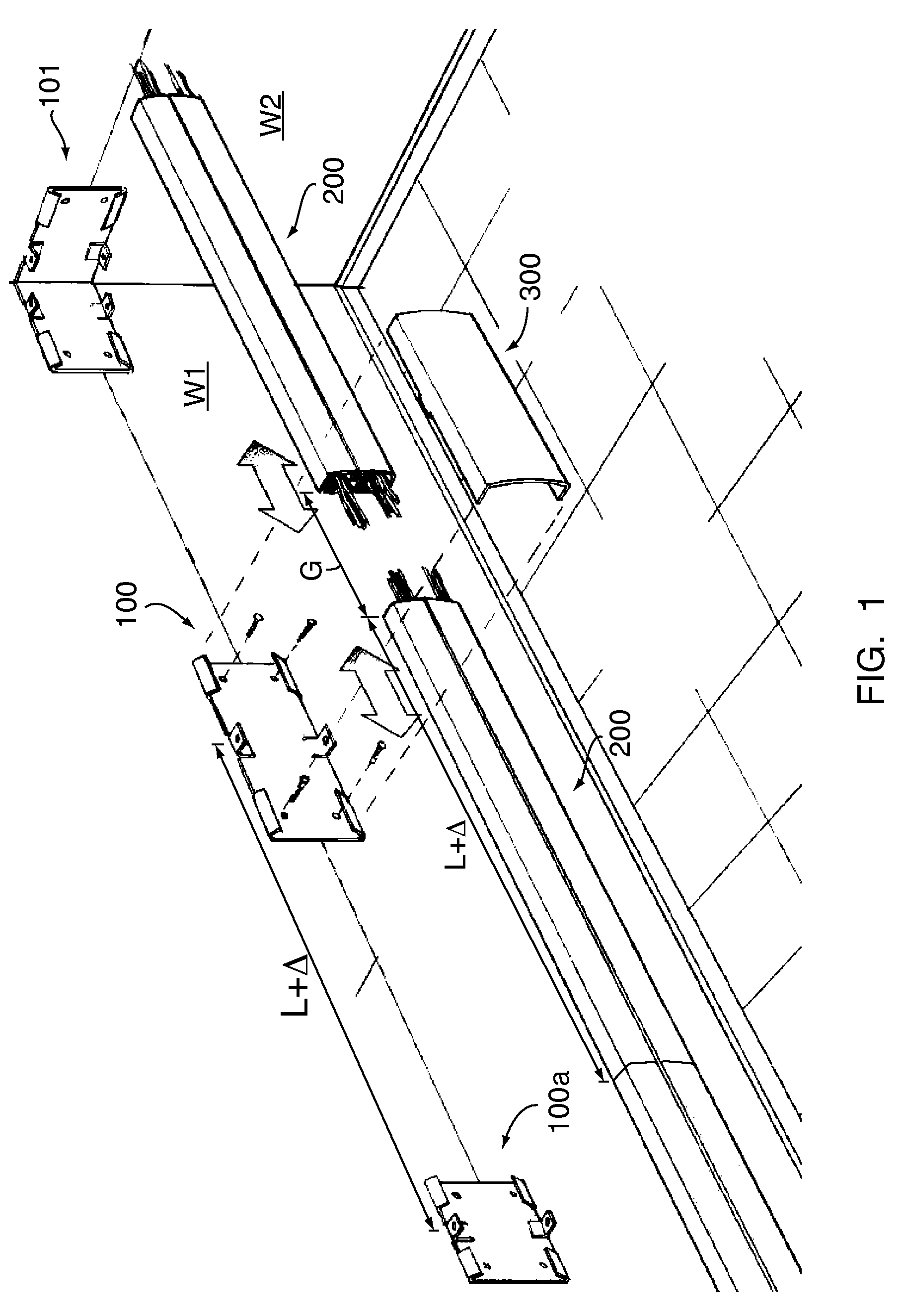
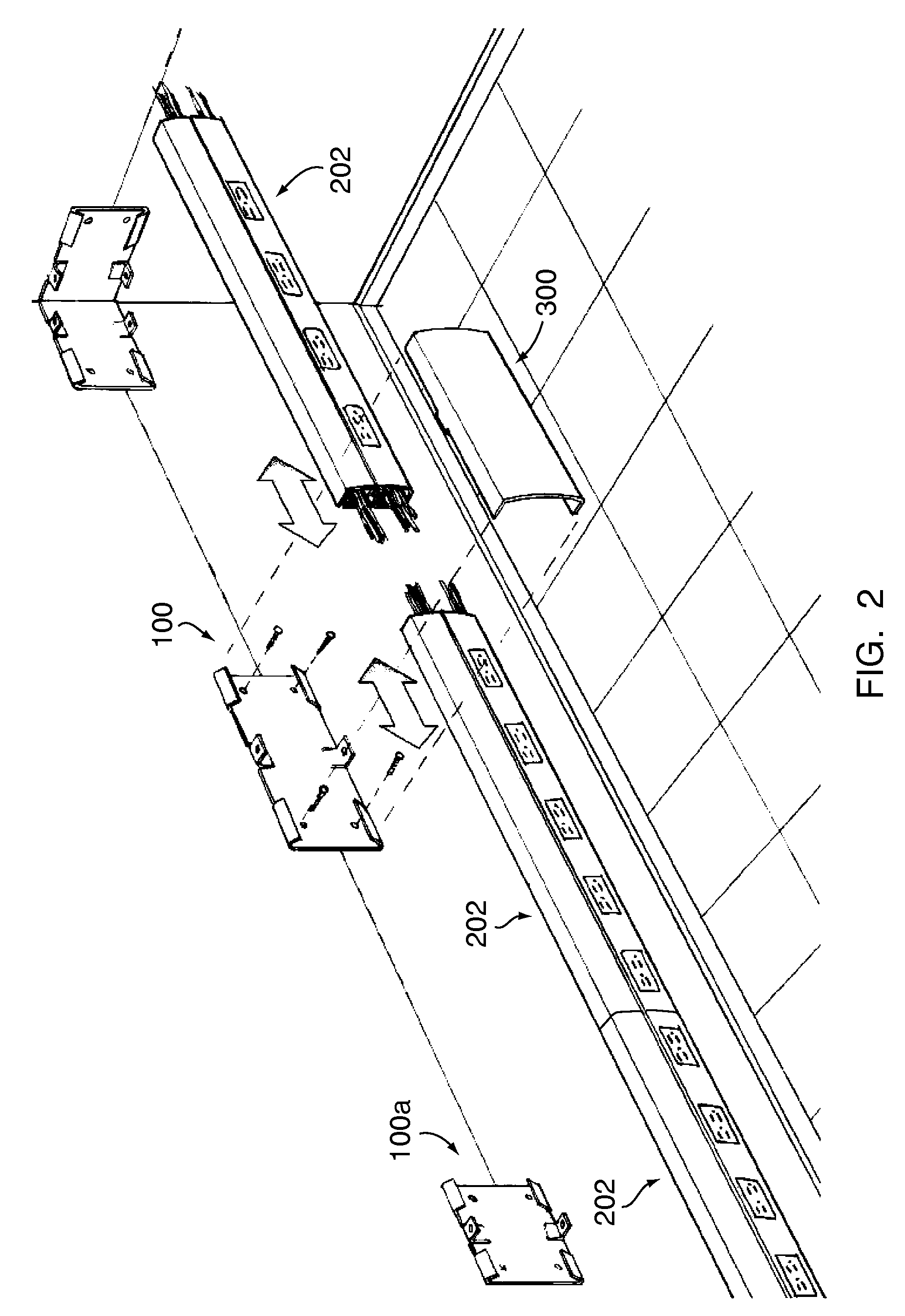
[0036]With reference to FIG. 1, in accordance with the first embodiment of the present invention, a modular raceway is provided, and includes standard-length raceway sections of length “L” that can be secured to the walls W1 or W2, by wall brackets as indicated at 100, 100a. Corner brackets can be fabricated from these unique wall brackets 100, as indicated at 101. Thus, the corner bracket 101 may comprise individual brackets fabricated from the wall brackets 100, 100a, to form a corner bracket 101. It will also be apparent that this same approach can be used to form a cor...


PUM


Abstract

Raceway modules of predetermined length are joined by couplers designed to allow optional gaps between the T-shaped raceway base plate portions. Upper and lower L-shaped raceway covers are separately snapped out the base, allowing electrical and data / communication devices to be provided in staggered relationship, and anywhere along the raceway. The lower L-shaped raceway cover configuration allows outlet devices to be provided in the lower side of the raceway. The T-shaped base plate has pre-punched knock-out openings and mounting holes provided in a predetermined pattern, and pre-punched lines of weakening, that simplify the installation process. The couplers come in several lengths and configurations, to bridge crossing raceway or other obstructions, and to provide continuity in the gaps between the raceway modules. Pre-wired cover components are fitted with spaced outlet devices for installation in areas of a room that require such service.

Description

CROSS-REFERENCE TO RELATED APPLICATION[0001]This application is a continuation of prior U.S. application Ser. No. 11 / 844,697, filed Aug. 24, 2007, which was a continuation of U.S. Pat. No. 7,262,371. The contents of said application and said patent are incorporated by reference herein.FIELD OF THE INVENTION[0002]The present invention relates to conduit or raceways for electrical cabling.BACKGROUND OF THE INVENTION[0003]In certain types of building construction, e.g., retrofits, cinder block, or the like, it may not be possible or practicable to run electrical cabling (such as high voltage power lines and low voltage data lines) through the building's walls. In such cases, modular raceway or conduit assemblies are often used to house and route cabling along a wall or other surface. A typical raceway assembly includes a linear or elongate housing having at least one interior passageway that accommodates a length of electrical cabling. (Such a passageway is referred to herein as a “wir...

Claims


Application Information

Patent Timeline
Patent Type & Authority Applications(United States)
IPC IPC(8): H02G3/08
CPCH02G3/0418H02G3/0431
Inventor MAKWINSKI, MARKPICARD, RICHARD R.HEMINGWAY, JEFFERYSTEMPINSKI, SHAWN
Owner THE WIREMOLD CO
Learn More