
System and method for optical multiplexing and/or demultiplexing

a fiber optic network and multiplexing technology, applied in the direction of optical elements, angle measurement, instruments, etc., can solve the problems of difficult alignment of source or target, complex and time-consuming manipulation of multiple interdependent components, and different alignment errors in each beam path, so as to improve the ease of manufacturing of optical devices, reduce manufacturing costs, and compact design

Inactive Publication Date: 2005-01-25
OPLINK COMM
View PDF40 Cites 11 Cited by
  • Summary
  • Abstract
  • Description
  • Claims
  • Application Information

AI Technical Summary

Benefits of technology

[0012]One aspect of the present invention provides an optical alignment element (OAE) that can be configured to substantially compensate for the cumulative alignment errors in the beam path. The OAE allows the optical elements in a device, other than the OAE, to be placed and fixed in place without substantially compensating for optical alignment errors. The OAE is inserted into the beam path and adjusted. This greatly increases the ease in the manufacturing of optical devices, especially for devices with numerous optical elements, and lowers the cost of manufacturing.
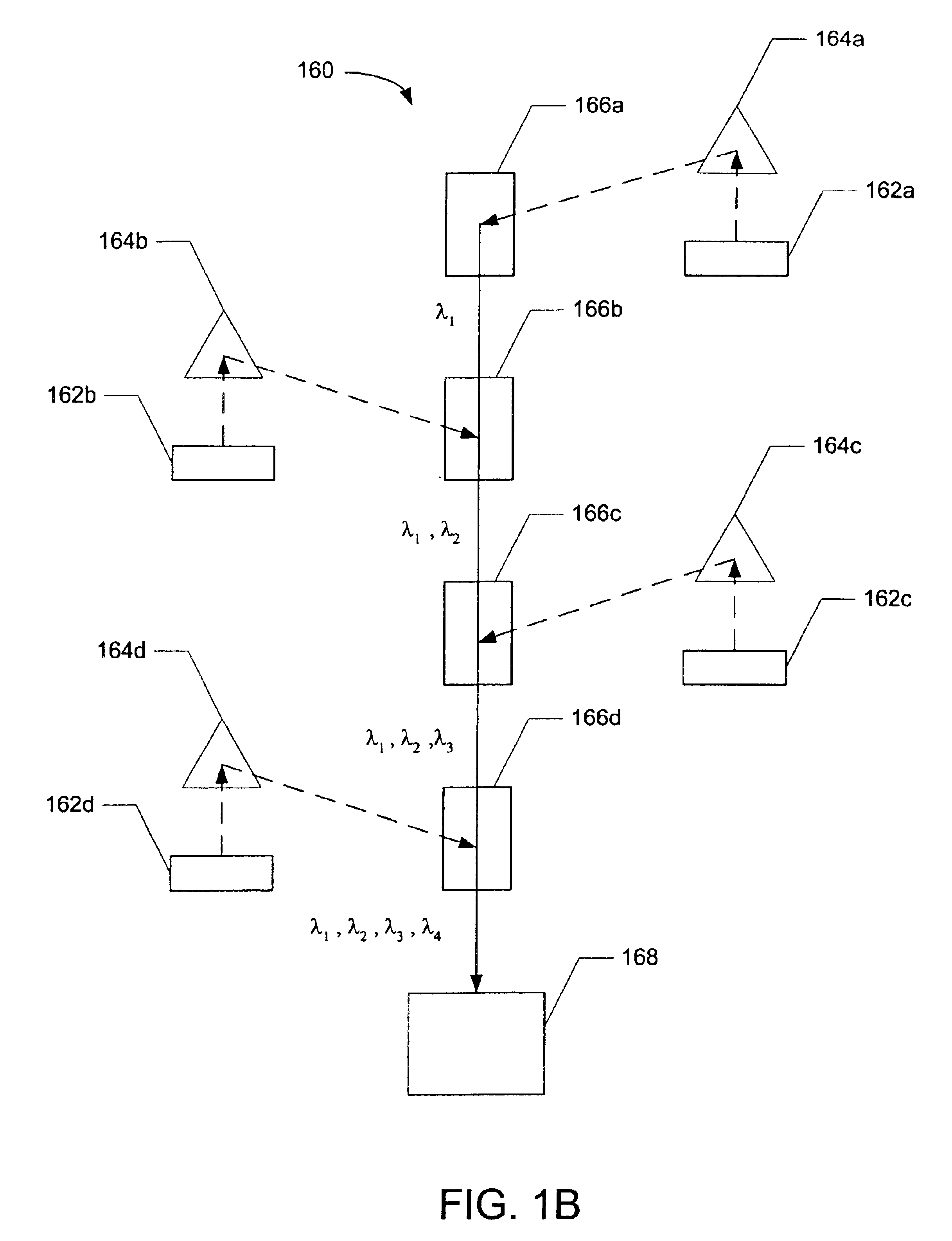
[0013]Another aspect of the present invention provides a compact multiplexer and / or demultiplex configuration which allows for the alignment of multiple folded beam paths to combine or separate optical channels. In one embodiment, a number of filters and mirrors are mounted on a core to route the beams. This aspect of the invention can be used to provide a very compact design and to permit flexibility in the placement of optical components. For instance, active components (such as lasers or optical receivers) may be positioned so that the electrical leads pass through the bottom of the device for convenient mounting to a printed circuit board, while an optical fiber which transmits or receives the optical signal from the network passes through the side of the device. The flexibility in routing, folding and aligning optical beams allows the components to be positioned conveniently for interfacing to external devices rather than being constrained by the alignment requirements of the device.
[0014]Another aspect of the present invention uses a compact form factor for a multiplexing device and / or demultiplexing device. The form factor may be a standard form factor typically used for a pluggable communications module which interfaces between serial transmission media and a host socket. These form factors may be defined for hot pluggable devices, such as receive optical sub-assemblies (ROSAs) and transmit optical sub-assemblies (TOSAs) in optical systems. Examples of these form factors include the GBIC form factor, the small form factor (SFF) and the small form pluggable (SFP) form factor. Aspects of the present invention provide for a compact multiplexer and / or demultiplexer using one of these form factors or an external housing and socket that is compatible with one of these form factors. This aspect of the invention can be used to provide a compact multiplexer and / or demultiplexer that can be inserted or removed from host sockets as part of a single module compatible with current host sockets used for ROSAs and TOSAs and thereby provide substantially more functionality with the same convenience.

Problems solved by technology

Precision alignment of an optical beam through optical devices and systems may pose a variety of challenges.
For instance, in optical multiplexing, a number of beams from different sources may need to be aligned with the tip of an optical fiber and each beam path may have different alignment error due to inaccuracies inherent in the fabrication and placement of optical components used in the device.
Manipulating multiple interdependent components may be complex and time consuming, and may be difficult due to the size and configuration of the system.
In addition, aligning the source or target can be difficult, since it may be electrically powered and have unique mounting or monitoring requirements.
However, it may be difficult to align the multiple dispersed channels with target fibers or other optical components intended to receive the separate channels.
Among other things, temperature changes may cause thermal expansion or contraction of components that result in alignment error.
Moreover, a long beam path may be required to achieve sufficient physical separation of the channels, which exacerbates alignment errors and may place limitations on the minimum size for the system.
However, a series of fiber loops may be required to route the signals to and from the filters, which can place limitations on the minimum size of the system.

Method used


Image

  • System and method for optical multiplexing and/or demultiplexing
  • System and method for optical multiplexing and/or demultiplexing
  • System and method for optical multiplexing and/or demultiplexing

Examples


Embodiment Construction

[0057]Improved methods and systems for routing and aligning beams and optical elements in an optical device are described below. The following description is presented to enable one of ordinary skill in the art to make and use the invention and is provided in the context of a patent application and its requirements. Various modifications to the preferred embodiment will be readily apparent to those skilled in the art and the generic principles herein may be applied to other embodiments. Thus, the present invention is not intended to be limited to the embodiment shown but is to be accorded the widest scope consistent with the principles and features described herein.

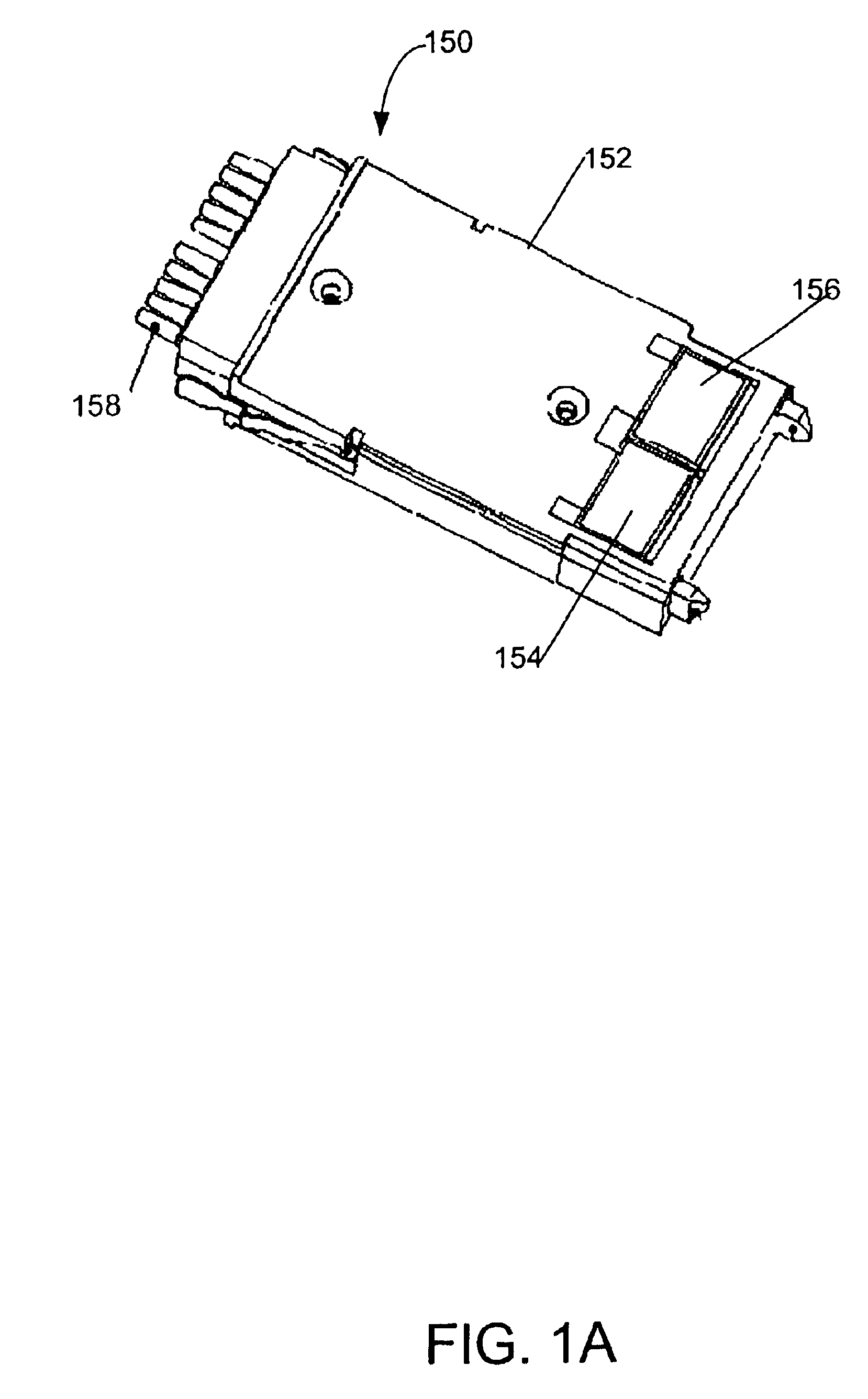
[0058]FIG. 1A illustrates an embodiment of WDM and WDDM devices in a GBIC form factor. The module 150 comprises the GBIC housing 152, which is part of the GBIC form factor, as defined by the GBIC specification. The module 150 may also comprise a connector which is compatible with the electrical interface defined by the GB...


PUM


Abstract

Improved methods and systems for routing and aligning beams and optical elements in an optical device include a multiplexing device and / or a demultiplexing device, which includes an optical alignment element (OAE). The OAE can be configured to substantially compensate for the cumulative alignment errors in the beam path. The OAE allows the optical elements in a device, other than the OAE, to be placed and fixed in place without substantially compensating for optical alignment errors. The OAE is inserted into the beam path and adjusted. This greatly increases the ease in the manufacturing of optical devices, especially for devices with numerous optical elements, and lowers the cost of manufacturing. The multiplexing and / or demultiplexing device can reside within a standard small form factor, such as a GBIC. The devices fold the paths of the traversing beams with a geometry which allows a small package.

Description

CROSS-REFERENCE TO RELATED APPLICATIONS[0002]This application is a Continuation-in-Part of co-pending U.S. patent application Ser. No. 09 / 916,624 entitled “Optical Alignment Element Method,” filed on Jul. 27, 2001. This application also claims priority from Provisional Application Ser. No. 60 / 350,407 entitled “System and Method for Optical Multiplexing and / or Demultiplexing,” filed on Jan. 18, 2002.FIELD OF THE INVENTION[0003]The field of the invention relates to routing and alignment of beams in an optical system and more particularly to systems and methods for wave division multiplexing and / or demultiplexing for a fiber optic network.BACKGROUND OF THE INVENTION[0004]Precision alignment of an optical beam through optical devices and systems may pose a variety of challenges. Devices may contain multiple optical elements, each having an associated alignment error that must be corrected. For instance, in optical multiplexing, a number of beams from different sources may need to be ali...

Claims


Application Information

Patent Timeline
Patent Type & Authority Patents(United States)
IPC IPC(8): G01B11/27G02B6/42G02B6/34
CPCG01B11/27G02B6/29311G02B6/29362G02B6/4227G02B6/2938G02B6/4215G02B6/29365
Inventor RICHARD, JENKIN A.CHAMNESS, ERIC V.GUAN, GEORGE H.KATARE, ANJUL K.BENEROFE, STEVEN J.LENG, QUNWEN
Owner OPLINK COMM
Learn More