Appliance remote control having separated user control and transmitter modules remotely located from and directly connected to one another

a remote control and transmitter technology, applied in the direction of electric controllers, programmers, instruments, etc., can solve the problems of user difficulty in programming such remote controls, user having to have access to user controls, and consuming a large amount of premium space, so as to facilitate user programming

Inactive Publication Date: 2007-01-18
LEAR CORP
View PDF99 Cites 12 Cited by
  • Summary
  • Abstract
  • Description
  • Claims
  • Application Information

AI Technical Summary

Benefits of technology

[0009] The present invention provides a universal remote control having a user control and a transmitter in which the remote control is programmable in such a way that the remote control does not have a radio frequency (RF) receiver and is relatively easier for a user to program and in which the user control and the transmitter are remotely located from one another and directly connected to one another by a wired connection, such as wiring or a part of a vehicle wiring harness, dedicated to the remote control.
[0021] The remote control in accordance with the present invention provides many advantages such as more flexibility in location placement of the user controls due to a smaller package of the user control module. The transmitter module can be placed in a location that provides optimum performance without the constraints of being conveniently accessible. More particularly, by separating the remote control into separate operating units (i.e., user control module and RF transmitter module), the transmitter module can be placed in a location optimal for RF transmission and the user control module can be placed in a convenient location for the vehicle driver without having to compromise or compete for larger packaging space. As such, the two module design makes it possible to develop a common transmitter module usable across many different platforms while developing a smaller user control module (i.e., a smaller button array) that provides more styling freedoms and more choices for location.
[0022] In general, in a vehicle, space is at a premium in the overhead consoles and visors, and mirrors that dictate special module designs to fit into the available spaces. The detached user control and transmitter modules design in accordance with the present invention requires much less packaging space thus making it easier to locate the user control module where space is an issue while locating the transmitter module in a remote location where space is not an issue. As such, for a vehicle, the remote control in accordance with the present invention provides styling flexibility and reduces packaging constraints in highly congested areas such as visors, overhead consoles, and mirrors.

Problems solved by technology

A problem with typical integrated remote controls is the difficulty experienced by users in programming such remote controls.
Another problem with typical integrated remote controls is that the receiver, transmitter, and user controls are packaged as a single unit as a result of the receiver and transmitter sharing the same RF components, the requirement of the user having to have access to the receiver to physically locate the receiver close enough to the original remote control or the existing transmitter for the learn or programming mode, and the requirement of the user having to have access to the user controls.
As such, this last requirement causes an additional problem in that the receiver and transmitter also have to be placed near the vehicle driver's seat where space is at a premium as they are physically packaged together with the user controls.
Accordingly, the receiver, transmitter, and user controls are packaged together as a single unit resulting in sub-optimal placement of the components as they are physically located together and near the vehicle driver's seat and further resulting in a relatively large amount of premium space being consumed as the single unit package has a relatively large size.

Method used


Image

  • Appliance remote control having separated user control and transmitter modules remotely located from and directly connected to one another
  • Appliance remote control having separated user control and transmitter modules remotely located from and directly connected to one another
  • Appliance remote control having separated user control and transmitter modules remotely located from and directly connected to one another

Examples


Embodiment Construction

)

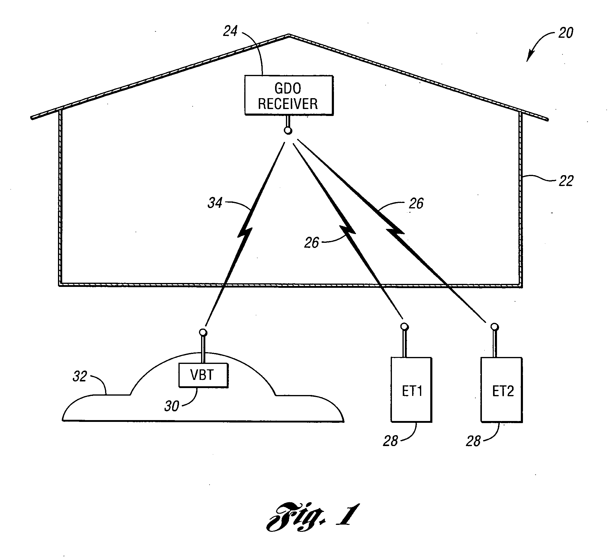
[0034] Referring now to FIG. 1, a block diagram illustrating an appliance control system 20 according to an embodiment of the present invention is shown. Appliance control system 20 allows one or more appliances to be remotely controlled using radio transmitters. In the example shown, radio frequency (RF) remote controls are used to operate a garage door opener (GDO). However, the present invention may be applied to controlling a wide variety of appliances such as other mechanical barriers, lighting, alarm systems, temperature control systems, etc.

[0035] Appliance control system 20 includes garage 22 having a garage door (not shown). A GDO receiver 24 receives RF appliance activation signals 26 for activating the garage door. Appliance activation signals 26 have a transmission scheme which may be represented as a set of receiver characteristics. One or more existing transmitters (ET) 28 generate appliance activation signals 26 exhibiting the receiver characteristics in response to...


PUM


Abstract

Vehicle-based programmable appliance control systems and methods include a user control module and a transmitter module which are remotely located from one another. A wired connection, such as a vehicle wiring harness, directly interconnects the modules. The wired connection has two ends and is assigned solely to the modules as the user control module is connected to one end of the wired connection and the transmitter module is connected to the other end of the wired connection. The user control module includes a user control and the transmitter module includes a radio frequency transmitter. The user control module transmits a user activation signal based on assertion of the user control to the transmitter module for receipt by the transmitter via the wired connection. The transmitter transmits a radio frequency appliance activation signal based on the received user activation signal in order to activate an appliance.

Description

CROSS-REFERENCE TO RELATED APPLICATIONS [0001] This application is a continuation-in-part of U.S. application Ser. No. 10 / 630,173, filed Jul. 30, 2003, which is hereby incorporated by reference in its entirety.BACKGROUND OF THE INVENTION [0002] 1. Field of the Invention [0003] The present invention relates to wireless remote control of an appliance such as a garage door opener (GDO). [0004] 2. Background Art [0005] Appliances such as garage door openers, security gates, home alarms, lighting, and the like may conveniently be activated from a remote control. Typically, a remote control is purchased together with an appliance. The remote control transmits a radio frequency (RF) appliance activation signal recognized by a receiver associated with the appliance to activate the appliance. [0006] An aftermarket remote control provides another remote control, in addition to the original remote control, for activating the appliance. Aftermarket remote controls include remote garage door ope...

Claims


Application Information

Patent Timeline
Patent Type & Authority Applications(United States)
IPC IPC(8): G08C19/00G08C17/02
CPCG08C17/02G08C19/28G08C2201/92G08C2201/31G08C2201/62G08C2201/20
Inventor MCCONNELL, JOHN E.NANTZ, JOHNSUMMERFORD, JASONBUCCINNA, FRANKCHUEY, MARK D.
Owner LEAR CORP
Why Eureka
Try Eureka