Method of transporting magnetic particles

a magnetic particle and magnetic field technology, applied in the direction of fluid speed measurement, moving filter element filter, optical light guide, etc., can solve the problems of increased production expenditure, high cost, and complete failure of assay, and achieve high rotational frequency, avoid cross contamination between different liquids, and more space

Active Publication Date: 2015-02-10
HAHN SCHICKARD GESELLSCHAFT FUER ANGEWANDTE FORSCHUNG EV
View PDF23 Cites 31 Cited by
  • Summary
  • Abstract
  • Description
  • Claims
  • Application Information

AI Technical Summary

Benefits of technology

[0016]Embodiments of the invention are thus based on an interaction of inertial and magnetic forces on a rotational body, for example a rotating substrate, and a stationary permanent magnet arranged in a certain manner, and allow, for the first time, magnetic particles to be transported between different, e.g. iso-radially arranged, chambers on the substrate across a liquid / gas interface. In addition to the drive for the rotational body, no additional actuation units and / or magnets are necessitated in the substrate for transporting the particles. This results in advantages in the manufacture with correspondingly lower cost and accelerated sequence operations in the implementation of biochemical protocols. Embodiments of the invention are suited, in particular, for unspecific DNA extraction by means of magnetic particles on a centrifugal-microfluidic platform. The inventive transport mechanism is thus suited, in particular, for many centrifugal-microfluidic diagnostics applications.
[0018]Unlike the conventional technology described, embodiments of the invention have numerous advantages. For example, according to U.S. 2008 / 0073546 A1, particles can only be moved within the same liquid phase, which necessitates that a second chamber has to be located further outward, in radial terms, as compared to the first chamber, so that more space will be necessitated in the radial direction. In addition, according to U.S. 2008 / 0073546 A1 for flushing the particles the valve with the particle trap has to be designed in such a robust manner that any reagents used may be retained during the mixing process, irrespective of their fluidic properties. Embodiments of the present invention avoid such disadvantages since such valves are not necessitated. In addition, according to U.S. 2008 / 0073546 A1, a substantial carry-over of liquid between the chambers takes place. In particular with highly sensitive biological assays (such as immunoassays, polymerase chain reaction, melting curve analysis, for example) even minor cross-contamination may lead to incorrect results or in complete failure of the assay. In embodiments of the invention, cross-contamination between different liquids may be reliably avoided. The method shown in U.S. 2008 / 0073546 A1 necessitates high rotational frequencies for mixing the magnetic particles as well as rotations in the clockwise and counter-clockwise directions, which increases the requirements in terms of the drive. Embodiments of the invention merely necessitate rotations in one rotational direction.

Problems solved by technology

In particular with highly sensitive biological assays (such as immunoassays, polymerase chain reaction, melting curve analysis, for example) even minor cross-contamination may lead to incorrect results or in complete failure of the assay.
Movable magnets in the disk has to be disposed of together with the disk, which results in higher cost and in increased production expenditure since the magnets have to be introduced during production.
Subsequent process steps are difficult or impossible to perform.

Method used


Image

  • Method of transporting magnetic particles
  • Method of transporting magnetic particles
  • Method of transporting magnetic particles

Examples


Embodiment Construction

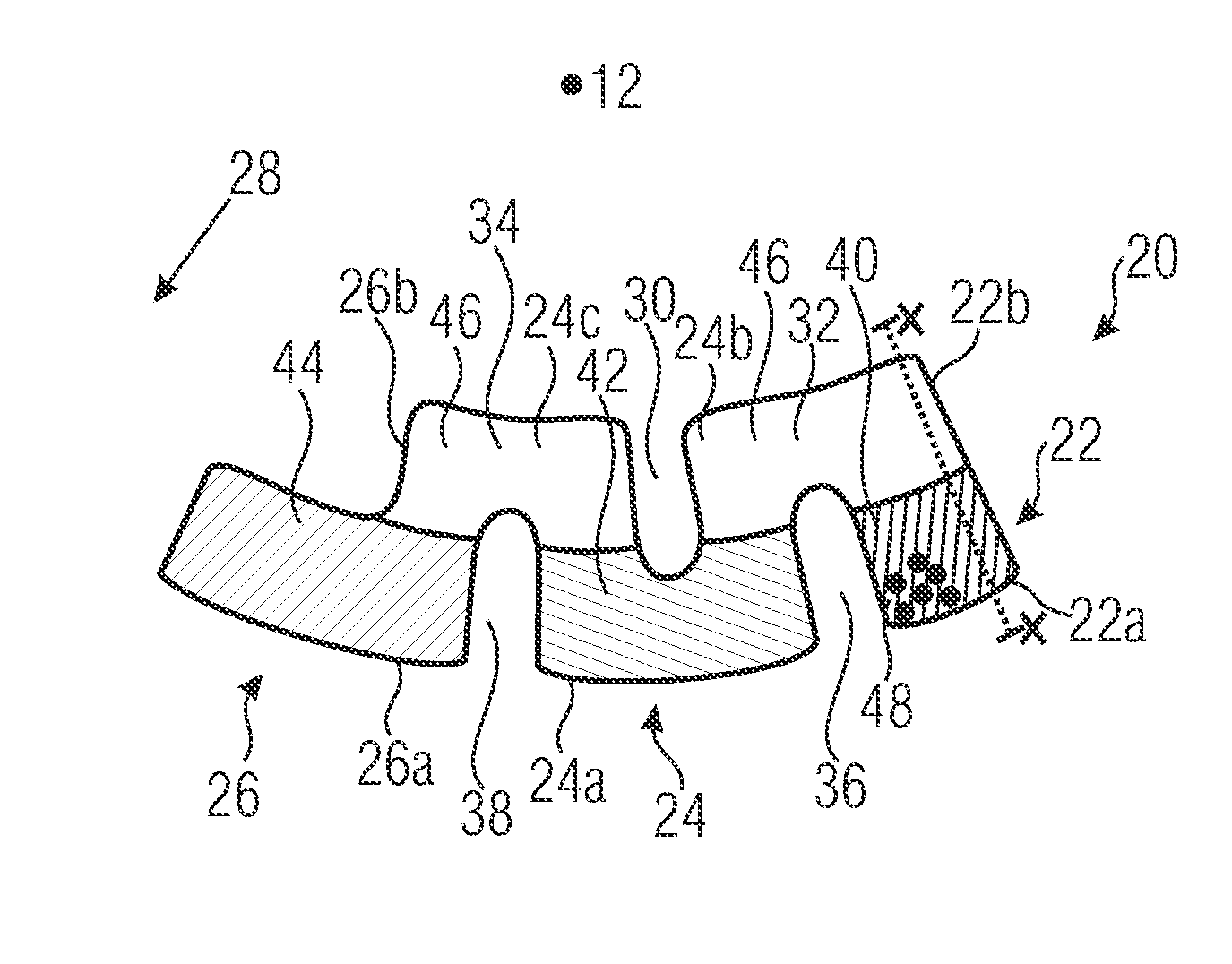
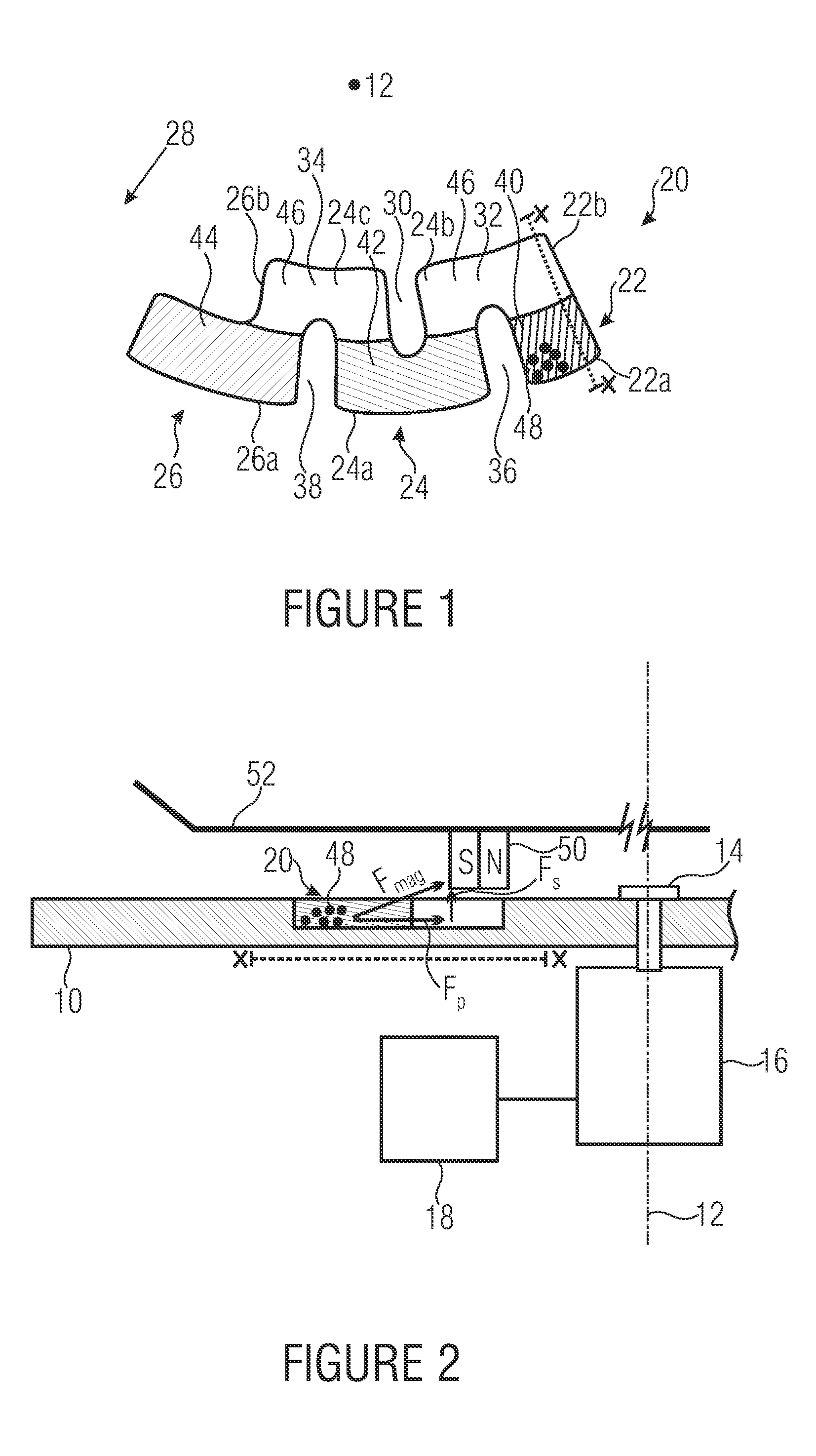
[0025]With regard to FIGS. 1 and 2, an embodiment of an inventive device for transporting magnetic particles will be explained in more detail below. The device includes a rotational body 10, for example in the form of a disk. Alternatively, the rotational body 10 might be formed by an insert that may be inserted into a rotational body, for example a disk. The rotational body 10 is rotatable about an axis of rotation 12, only the left-hand side of the rotational body 10 being fully depicted in FIG. 2. Via a coupling means 14, the rotational body 10 is coupled to a motor 16, which represents a drive for the rotational body 10. The coupling means may be structured in a common manner known to persons skilled in the art. The motor 16 is connected to a controller 18 designed to control the motor 16 in order to allow magnetic particles to be transported in the inventive manner. The controller may be implemented in hardware or in software and may be configured to provide suitable drive sign...


PUM

PropertyMeasurementUnit
radial heightaaaaaaaaaa
rotational frequenciesaaaaaaaaaa

Abstract

A method of transporting magnetic particles enables magnetic particles to be transported between a plurality of microfluidic chambers which are connected to one another via a fluidic connection on a radially inner side, and are fluidically separated from one another on a radially outer side. Magnetic forces and centrifugal forces are exploited to transport magnetic particles from one chamber to another across phase boundaries.

Description

CROSS-REFERENCE TO RELATED APPLICATIONS[0001]This application is a continuation of copending International Application No. PCT / EP2011 / 066672, filed Sep. 26, 2011, which is incorporated herein by reference in its entirety, and additionally claims priority from German Application No. 102010041621.5, filed Sep. 29, 2010, which is also incorporated herein by reference in its entirety.BACKGROUND OF THE INVENTION[0002]The present invention relates to a method of transporting magnetic particles, and in particular to a method of transporting magnetic particles from a first liquid into a second liquid, which is not significantly in fluidic contact with the first liquid.[0003]Microfluidic systems are becoming increasingly important, in particular in the fields of medicinal and molecular diagnostics applications, the term μTAS (micro total analysis system), among others, having been coined for such systems. Please see, for example, A. Manz, N. Graber, and H. M. Widmer, “Miniaturized Total Chem...

Claims


Application Information

Patent Timeline
Patent Type & Authority Patents(United States)
IPC IPC(8): B03C1/00G01N35/00B81B1/00B03C1/02B01L3/00
CPCB03C1/02B01L3/502761G01N35/00069B81B1/00B01L2200/0668B01L2300/087B01L2300/0883B01L2400/0409B01L2400/043Y10T436/111666Y10T436/25375
Inventor STROHMEIER, OLIVERVON STETTEN, FELIXMARK, DANIEL
Owner HAHN SCHICKARD GESELLSCHAFT FUER ANGEWANDTE FORSCHUNG EV
Why Eureka
Try Eureka