Hard disk drive casing

Active Publication Date: 2015-02-10
ECHOSTREAMS INNOVATIVE SOLUTIONS
View PDF9 Cites 14 Cited by
  • Summary
  • Abstract
  • Description
  • Claims
  • Application Information

AI Technical Summary

Benefits of technology

[0007]The object of the instant disclosure is to improve upon structural strength and exc

Problems solved by technology

However, hard drives are fragile electronic products that cannot withstand substantial amount of impact du

Method used


Image

  • Hard disk drive casing
  • Hard disk drive casing
  • Hard disk drive casing

Examples


Example

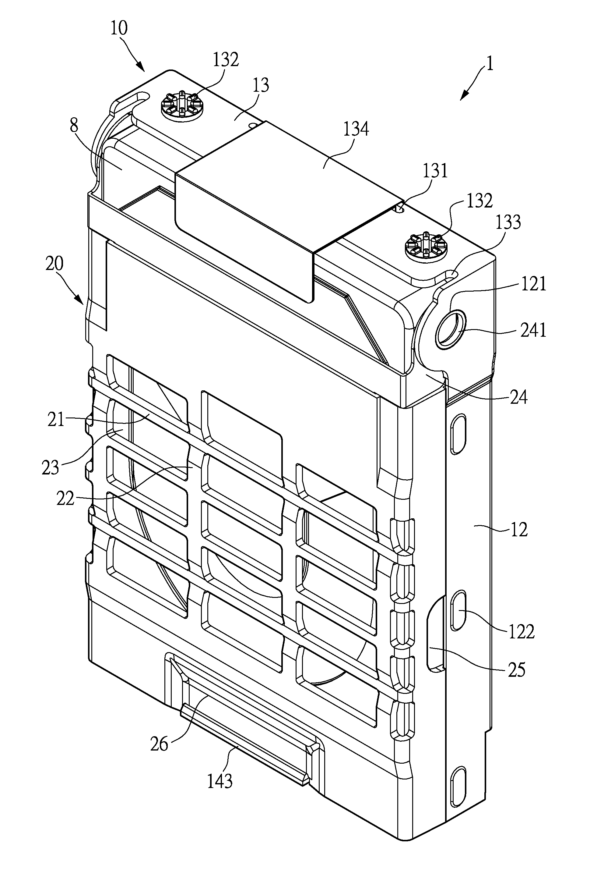
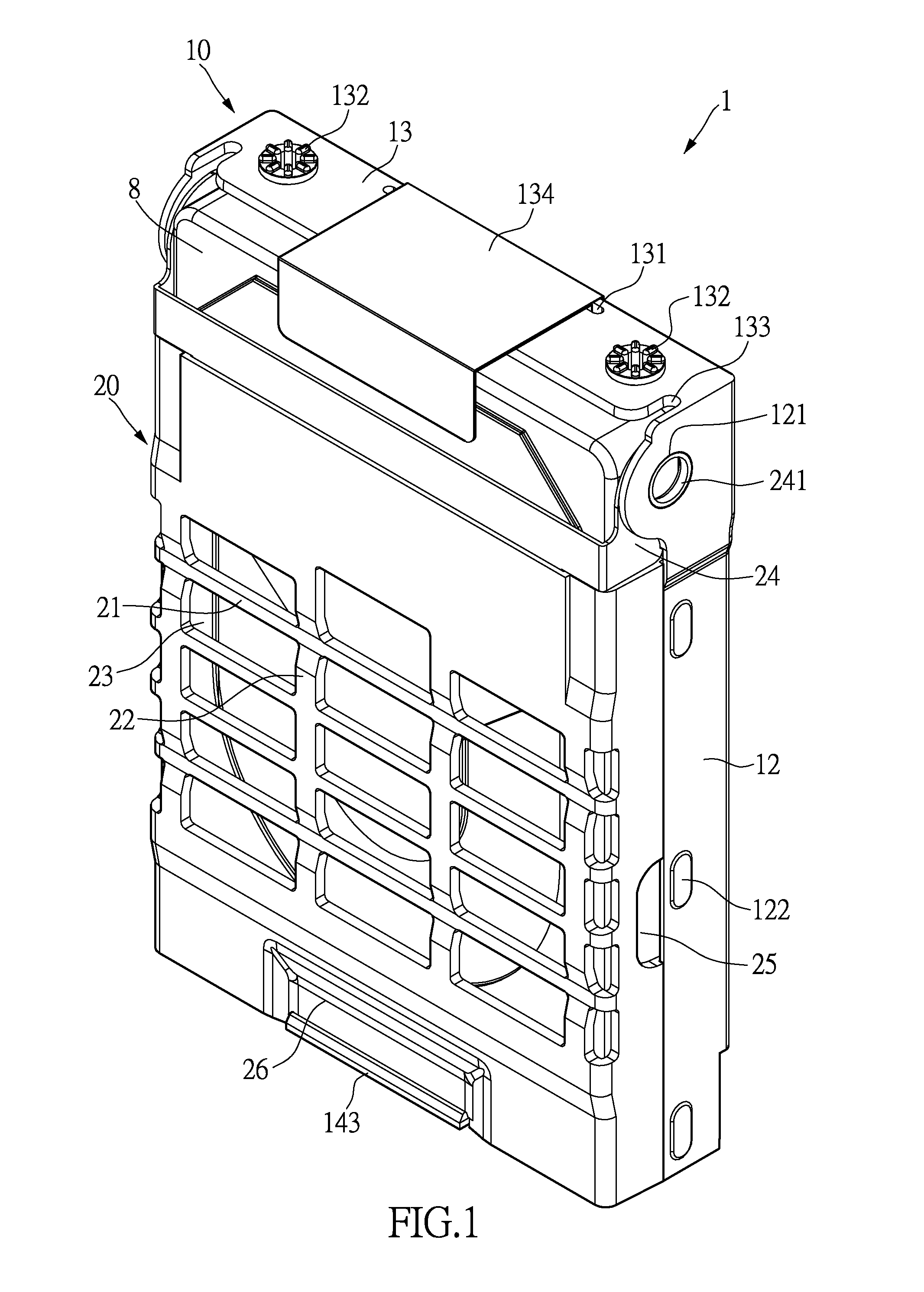
[0020]As shown in FIG. 1, the instant disclosure provides a hard drive casing 1 for accommodating a hard drive 8 therein, such that the hard drive 8 can be securely installed in a server case body 9 (As shown in FIG. 9). As shown in FIG. 1, the hard drive casing 1 includes a case body 10 and a cover body 20. The cover body 20 is pivotably coupled to and covers the case body 10. The hard drive 8 can be disposed in the case body 10, and the cover body 20 secures the hard drive 8 in the case body 10.

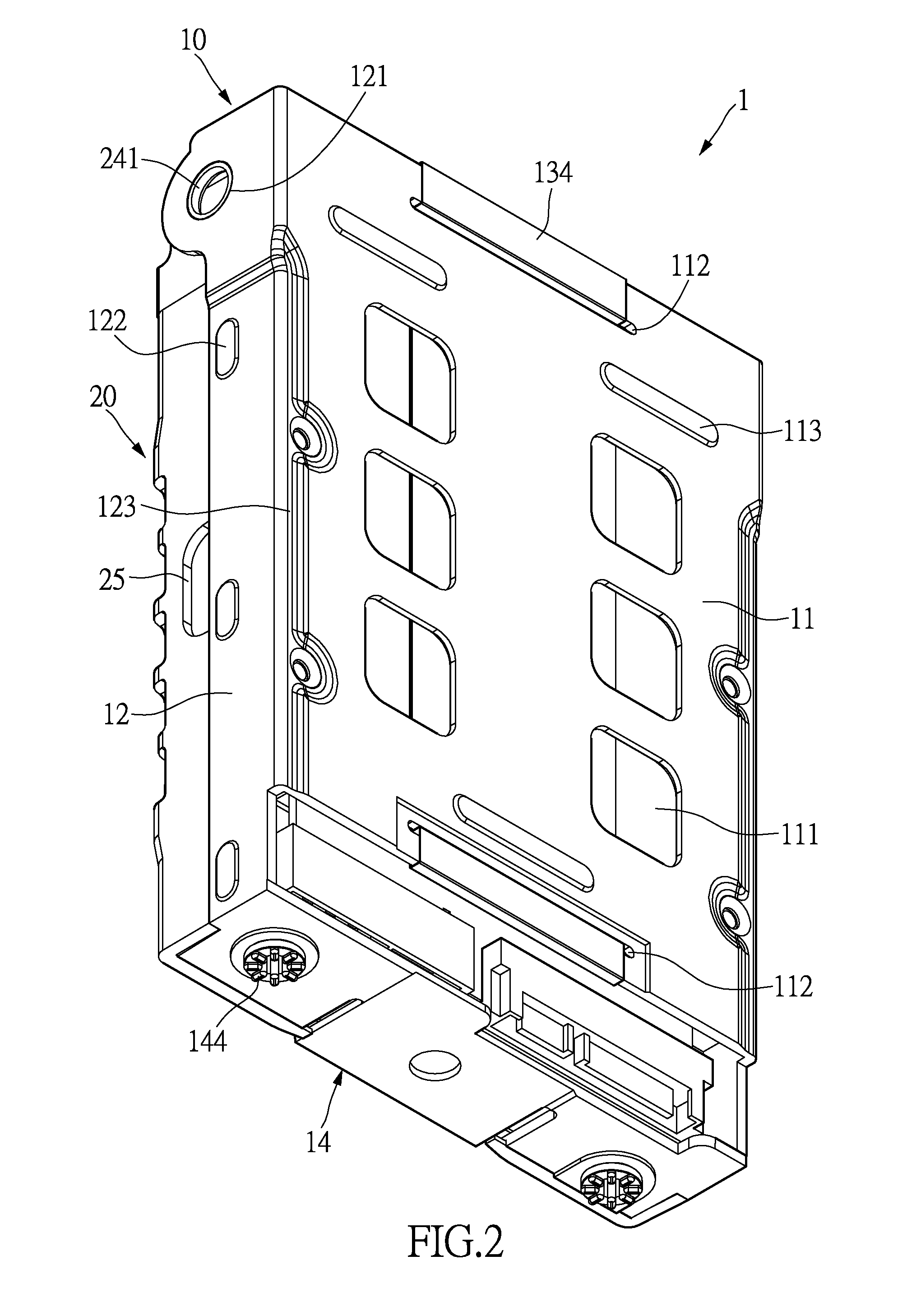
[0021]As shown in FIGS. 2 and 3, the case body 10 is formed by a base wall 11 and a peripheral wall arranged around the base wall 11, such that the case body 10 resembles a case-like body without a cover. The peripheral wall surrounding the base wall 11 is divided into two pivoting walls 12, a pull-wall 13 and a coupling wall 14. As shown in FIG. 3, the two pivoting walls 12 are two oppositely faced sidewalls, the pull-wall 13 is an upper wall, and the coupling wall 14 is a lower wall as sh...


PUM


Abstract

A hard drive casing for accommodating a hard drive includes a case body and a cover body. The cover body has a base wall and a peripheral wall surrounding the base wall. The case body accommodates the hard drive therein. The peripheral wall has a handle arranged on an outer surface thereof. The cover body is adapted to cover the case body. The cover body is pivotally coupled to the case body. The cover body has a plurality of ribs arranged thereon. The ribs protrude towards the case body. The ribs and the base wall define a gap therebetween, and the gap has a width smaller than a thickness of the hard drive.

Description

BACKGROUND OF THE INVENTION[0001]1. Field of the Invention[0002]The instant disclosure relates to a case body for accommodating a hard disk drive or a hard drive; in particular, to a case body for depositing in a chassis.[0003]2. Description of Related Art[0004]Network servers and data storage equipment are essential for the provision of cloud services. Typically, hard drives are installed through the front of a server cabinet and supported by brackets in order to provide high volume of data storage and expansion. For example, the current server tower or chassis for accommodating hard drives first disposes the hard drive into a hard drive housing, then the hard drive and the housing are both inserted into the chassis for installation on support brackets.[0005]However, hard drives are fragile electronic products that cannot withstand substantial amount of impact due to shaking and vibrations caused by gaps between the conventional hard drive housing and the hard drive. In order to en...

Claims


Application Information

Patent Timeline
IPC IPC(8): G11B17/00G06F1/16
CPCG06F1/187G11B33/022G11B33/124G11B33/128
Inventor LEE, CHENG-CHULEE, GENE JINGLUENCHU, CHANG-FENG
Owner ECHOSTREAMS INNOVATIVE SOLUTIONS
Why Eureka
Try Eureka