Device for releasing a transceiver fixed in a housing via a connection from the housing

a technology for transceivers and housings, which is applied in the direction of instruments, liquid handling, manufacturing tools, etc., can solve the problems of not being able to use known protective housings for lc plugs in appliances, etc., to achieve quick and easy replacement

Active Publication Date: 2015-02-17
MC TECH GMBH (DE)
View PDF13 Cites 75 Cited by
  • Summary
  • Abstract
  • Description
  • Claims
  • Application Information

AI Technical Summary

Benefits of technology

[0012]An aspect of the present invention is to provide a device for releasing a transceiver fixed in a housing via a connection from the housing which has first means by which the device can be releasably connected to the transceiver; and, furthermore, it has second means for releasing the connection between the transceiver and the housing. Thus, this device can be connected to the transceiver, which is mounted in the housing, but which is at least partly accessible from the outside of the appliance housing, and furthermore the connection between the transceiver and the housing is released so that with the help of the device the transceiver can be pulled out from the housing without having to open the device housing. The connection between the device and the transceiver can then be released once again. In this way, even with dust and water proof appliance housings the transceiver can be quickly and easily replaced from outside the appliance.
[0017]Another aspect of the present invention is to provide an embodiment wherein, the second means are configured as a wedge, with which it is possible in an especially easy way to release the connection, especially a locking connection, between the transceiver and the housing and pull the device with the transceiver out from the housing, without the connection, especially the locking connection, between transceiver and housing becoming reengaged.
[0018]Advantageously, the second means are configured as a hook element, which engages in particular with a strap arranged on the transceiver or a lever arranged on the transceiver, so that when the device is pulled out the connection, especially the locking connection, between the transceiver and the housing is easily released.
[0019]Basically, it is possible for the first means and the second means of the device to move relative to each other, so that, for example, after inserting the device into the plug contour of the transceiver, the second means can be operated separately in order to release the connection between the transceiver and the housing, or also a releasing of the connection between the transceiver and the housing first occurs through the second means and then the first means are inserted into the plug contour. According to an especially preferred embodiment of the invention, the first means and the second means are, however, arranged relative to each other on the device so that when the first means are inserted into the plug contour of the transceiver at the same time the connection between the transceiver and the housing is released by the second means, enabling an especially easy handling of the device. According to an alternative preferred embodiment of the invention, after connecting the device to the transceiver via the first means the connection between the transceiver and the housing is released by the second means when pulling out the device. This also enables an especially easy handling of the device.
[0021]In another aspect of the present invention, the device is configured as a single piece, to enable a simple and economical production process.
[0022]Advantageously, the device is made by the plastic injection molding process, which enables a simple and economical production process.

Problems solved by technology

Such a transceiver with a lever, a stirrup or a strap has a large size, however, so that it cannot be used with known protective housings for LC plugs in appliances that are supposed to be dust or waterproof.
Therefore, the problem to be solved is to make it possible to release a transceiver locked in a housing from outside the device, where in particular a small size of the transceiver should be made possible.
What is not appreciated by the prior art is that transceivers having a lever, a stirrup or a strap as described hereinabove are of a relatively large size, however, so that they cannot be used with known protective housings for LC plugs in appliances that are supposed to be dust or water proof.

Method used


Image

  • Device for releasing a transceiver fixed in a housing via a connection from the housing
  • Device for releasing a transceiver fixed in a housing via a connection from the housing
  • Device for releasing a transceiver fixed in a housing via a connection from the housing

Examples


Embodiment Construction

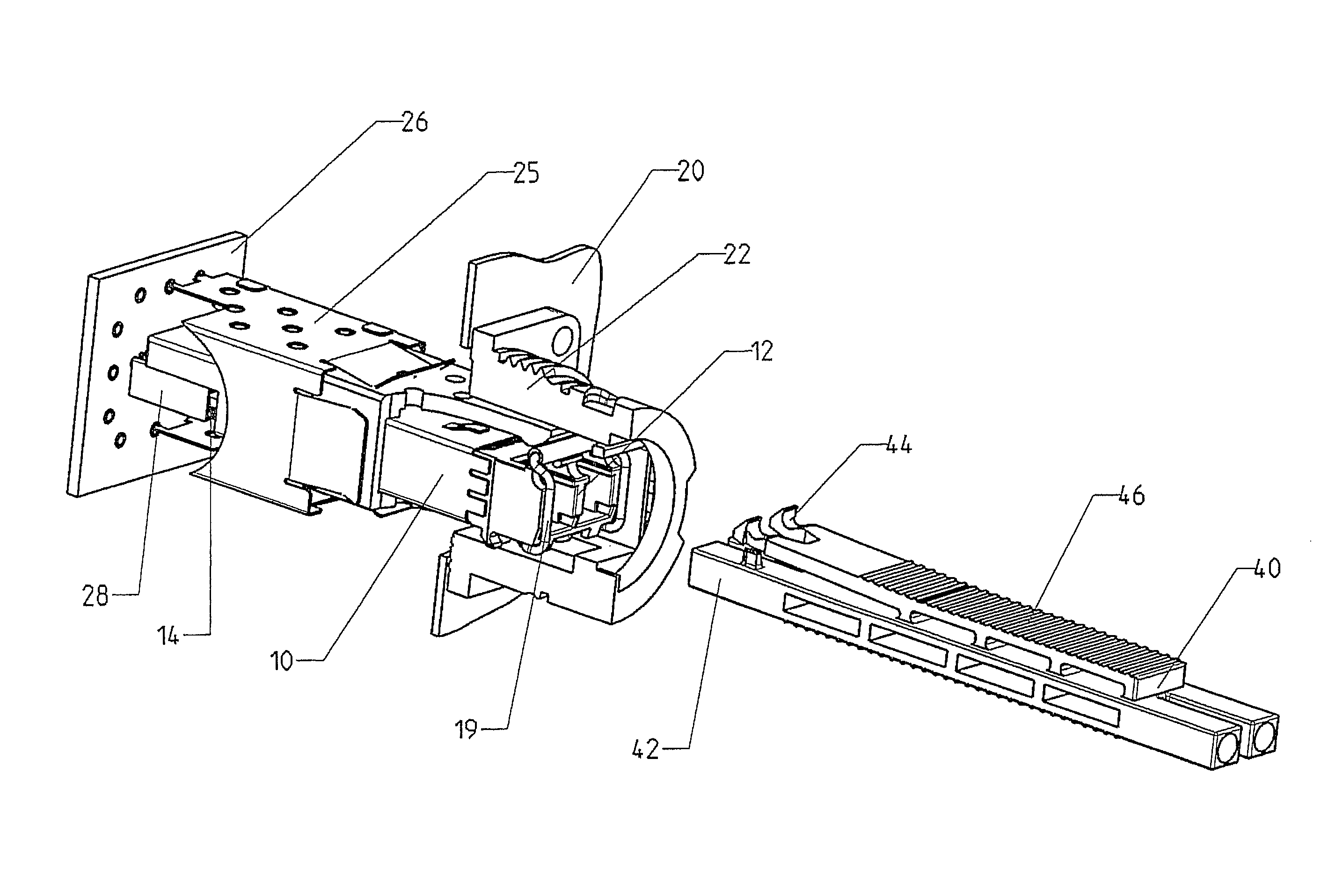
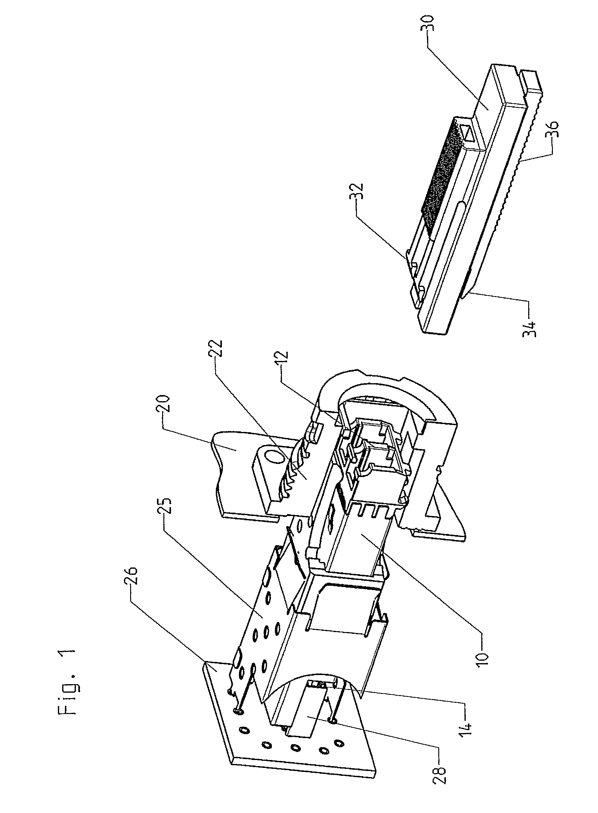
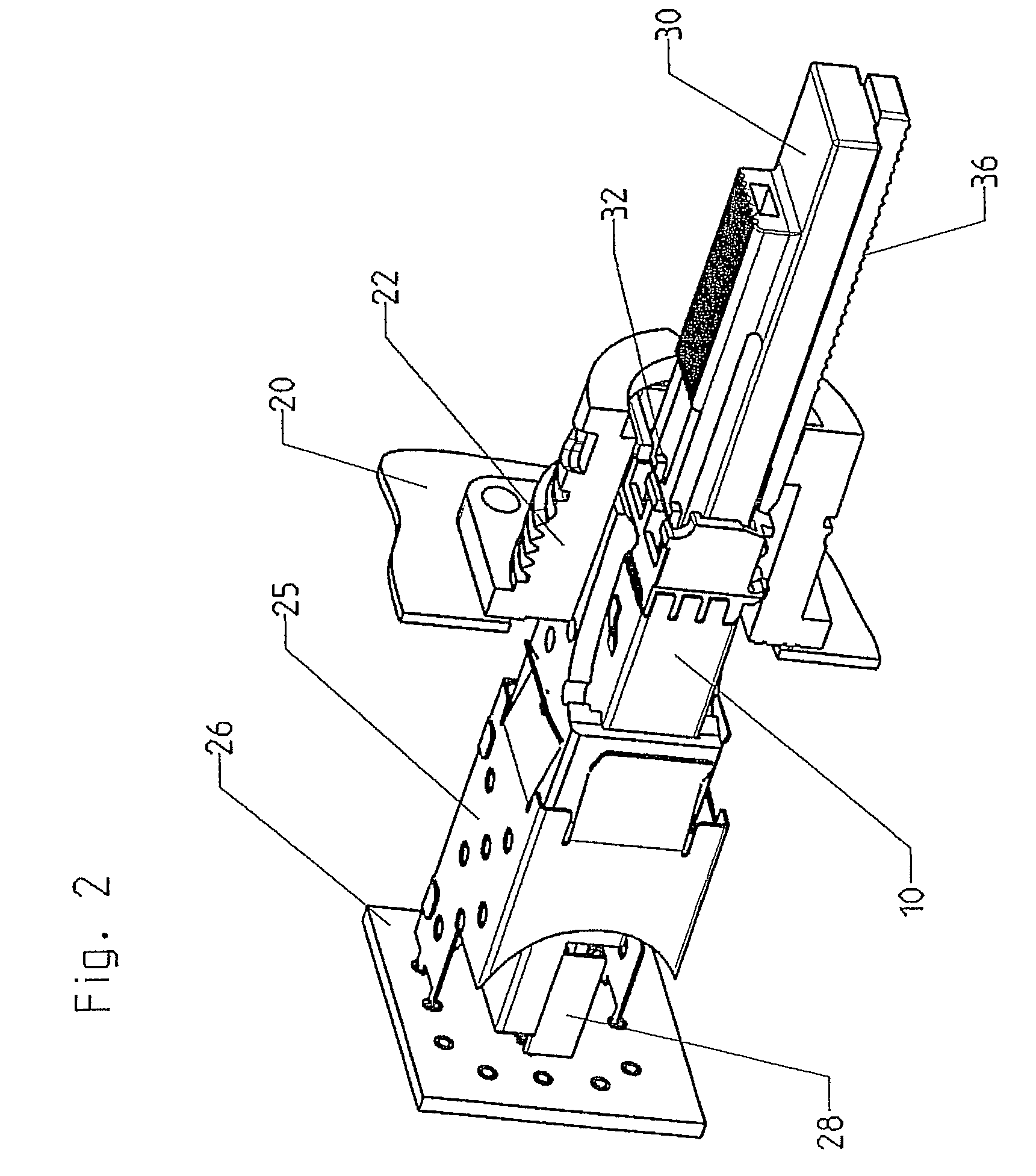
[0032]Reference will now be made in detail to several embodiments of the invention that are illustrated in the accompanying drawings. Wherever possible, same or similar reference numerals are used in the drawings and the description to refer to the same or like parts or steps. The drawings are in simplified form and are not to precise scale. For purposes of convenience and clarity only, directional terms, such as top, bottom, up, down, over, above, and below may be used with respect to the drawings. These and similar directional terms should not be construed to limit the scope of the invention in any manner. The words “connect,”“couple,” and similar terms with their inflectional morphemes do not necessarily denote direct and immediate connections, but also include connections through mediate elements or devices.

[0033]FIGS. 1 through 3 show various representations of a first sample embodiment, wherein for better visibility not all reference numbers are given in all figures. The same ...


PUM

PropertyMeasurementUnit
timeaaaaaaaaaa
electricalaaaaaaaaaa
diameteraaaaaaaaaa

Abstract

The invention concerns a device for releasing a transceiver, fixed in a housing via a connection, from the housing, wherein the device is releasably connectable and insertable into a plug contour of the transceiver via first means and wherein the device has second means for releasing the connection between the transceiver and the housing.

Description

CROSS REFERENCE TO RELATED APPLICATIONS[0001]This application claims priority from German Patent Application Serial No. 10 2009 020 188.2-34, filed May 7, 2009, the entire contents of which is herein incorporated fully by reference.FIGURE FOR PUBLICATION[0002]FIG. 1.BACKGROUND OF THE INVENTION[0003]1. Field of the Invention[0004]The present invention relates to a device for releasing a transceiver fixed in a housing via a connection from the housing. More specifically, the present invention relates to small form factor pluggable optical transceivers which can be releasably locked within a housing and can be released via an external connection having first and second releasing means for causing the transceiver to be released.[0005]2. Description of the Related Art[0006]The related art involves so-called “transceivers,” i.e., combinations of a transmitter and a receiver configured as a structural unit. Optical transceivers are especially familiar, which transfer light injected by opti...

Claims


Application Information

Patent Timeline
Patent Type & Authority Patents(United States)
IPC IPC(8): G02B6/36B23P19/00B25B7/12B67B7/00G02B6/38G02B6/42
CPCG02B6/4246G02B6/4201G02B6/3898G02B6/4261G02B6/4284G02B6/4292H01R43/26Y10T29/53283
Inventor ROSCH, WERNER
Owner MC TECH GMBH (DE)
Why Eureka
Try Eureka