Tunnel-type rotary-drum tumble dryer

a rotary-drum, dryer technology, applied in the direction of dryers with non-progressive movements, dryers, textiles and papermaking, etc., can solve the problems of reducing dryer efficiency, difficult for hot air circulating inside the dryer to pass through clothing to be dried, and inefficient hot air circulation through perforations, etc., to achieve effective drying action, reduce energy expenditure, and increase the tendency of clothing

Active Publication Date: 2015-02-24
GIRBAU SA
View PDF13 Cites 1 Cited by
  • Summary
  • Abstract
  • Description
  • Claims
  • Application Information

AI Technical Summary

Benefits of technology

[0009]The flow of drying air from the air inlet to the air outlet inside the drum in an axial direction through the clothing tumbling therein provides a more effective drying action with less energy expenditure in the tumble dryer of the present invention compared with dryers of the prior art. The present invention further contemplates using the air inlet and outlet arrangement creating a flow of air inside the drum in an axial direction opposite the movement of the clothing in combination with an inclined arrangement of the drum to provide an automatic device for unloading the clothing from the drum.
[0010]Thus, in one embodiment, the drum is configured and arranged such that any generatrix of the revolution wall of the drum which is at the lowest level of the drum is inclined with an end adjacent to the end opening facing the loading door more elevated than the other end adjacent to the end opening facing the unloading door. This can be achieved for example by means of a cylindrical revolution wall arranged with the geometric axis inclined with respect to the horizontal or by means of a frustoconical revolution wall arranged with the geometric axis horizontal or inclined with respect to the horizontal. Due to the mentioned inclination of the lower generatrix of the drum, during a drying operation and as a result of the rotation of the drum the clothing has the tendency to move towards the end opening of the drum facing the unloading door, and the flow of drying air inside the drum in the axial direction from the end adjacent to the unloading door to the end adjacent to the loading door offsets said tendency of the clothing to move towards the end opening of the drum facing the unloading door and keeps the clothing tumbling inside the drum. Once the clothing is dry, with the air circulation means stopped and the unloading door open, the simple rotation of the drum in the absence of the flow of air in the opposite direction moves the clothing towards the unloading door and automatically unloads the clothing from the drum.
[0011]This automatic unloading device can be used in combination with oblique or helical inner blades fixed to an inner surface of the revolution wall of the drum contributing to offset the tendency of the clothing to move towards the end opening facing the unloading door when the drum rotates in a first direction and contributing to increase the tendency of the clothing to move towards the end opening facing the unloading door when the drum rotates in a second opposite direction.

Problems solved by technology

One drawback is that the passage area of the perforations is relatively small compared with the area of the cylindrical wall and this means that the hot air circulation through the perforations is not very efficient and that a large part of the flow circulates around the drum without penetrating therein.
One drawback of this construction is that the items to be dried, which, as a result of the rotation of the drum tumble on the areas of the drum which are at a lower level, have the tendency to block the perforations of the wall of the drum in these areas located at a lower level forcing the hot air to enter and exit the drum through the perforations of the areas of the drum which are at a higher level, which makes it difficult for the hot air circulating inside the drum to pass through the clothing to be dried and this reduces dryer efficiency.

Method used


Image

  • Tunnel-type rotary-drum tumble dryer
  • Tunnel-type rotary-drum tumble dryer
  • Tunnel-type rotary-drum tumble dryer

Examples


Embodiment Construction

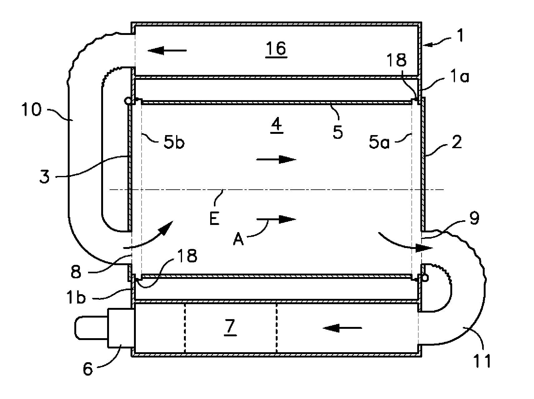
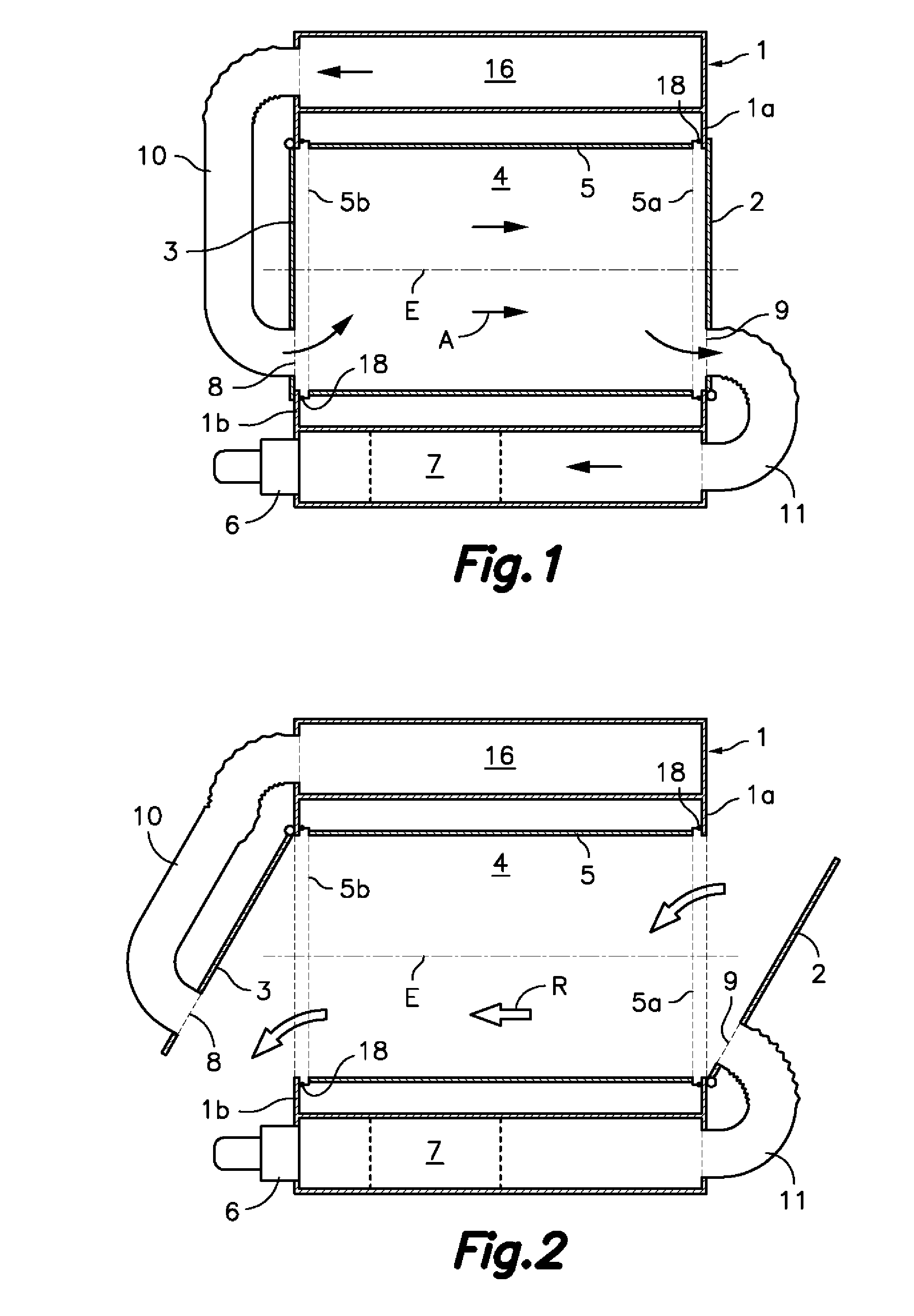
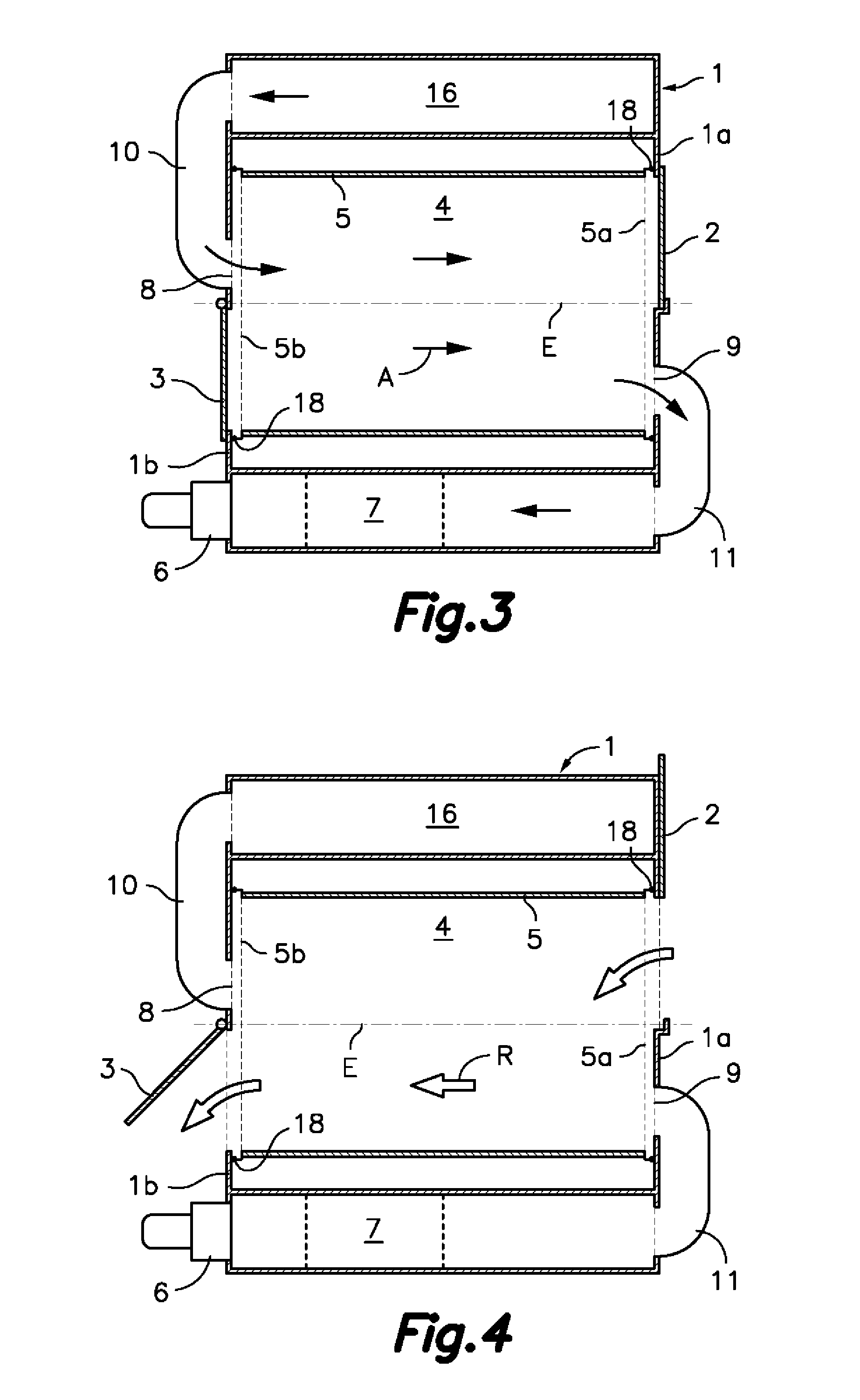
[0021]First referring to FIGS. 1 and 2, the tunnel-type rotary drum tumble dryer according to the first embodiment of the present invention comprises a cabinet 1 having an upper wall, a lower wall and opposite lateral walls 1a, 1b in which respective opposite loading and unloading openings are formed. The mentioned loading opening on one side can be closed by means of a loading door 2 and said unloading opening on the opposite side can be closed by means of an unloading door 3. Inside said cabinet 1 there is arranged a drum 4 for containing clothing to be dried which can rotate with respect to a horizontal geometric axis E under the action of driving means. The mentioned drum 4 has a revolution wall 5 around said geometric axis E and end openings 5a, 5b at opposite ends. One of said end openings 5a of the drum 4 is facing the loading door 2 and the other end opening 5b is facing the unloading door 3. End edges of the revolution wall 5 revolving around the end openings 5a, 5b of the ...


PUM


Abstract

A tunnel-type rotary drum tumble dryer includes a cabinet (1) with a loading door (2) and an unloading door (3) on opposite sides, and a drum (4) arranged inside the cabinet (1) for rotating with respect to a horizontal or inclined geometric axis (E). The drum (4) has a revolution wall (5) around the axis (E), and end openings (5a, 5b) at opposite ends facing said loading and unloading doors (2, 3). The tumble dryer also includes an air circulator that includes an air inlet (8) facing one of the end openings (5a, 5b) of the drum (4) and an air outlet (9) adjacent to the other end opening (5a, 5b) of the drum (4) for creating an axial flow of drying air inside and from one end to another of the drum (4) through the clothing tumbling inside the drum (4).

Description

FIELD OF THE ART[0001]The present invention relates to a tunnel-type rotary drum tumble dryer where the drum is arranged for rotating with respect to a horizontal or inclined geometric axis and has a revolution wall around said geometric axis and end openings at opposite axial ends, and where the clothing to be dried is loaded into the drum through one of said end openings and unloaded through the other opposite end opening. The tumble dryer of the present invention has a special application in the industrial laundry field.BACKGROUND OF THE INVENTION[0002]Tumble dryers provided with a cabinet inside which there is installed a tunnel-type rotary drum arranged for rotating with respect to a horizontal or inclined geometric axis are well known in the prior art. The tunnel-type drum is provided with a perforated cylindrical wall and with end openings at opposite axial ends. These end openings of the drum are facing corresponding loading and unloading openings formed in the cabinet, whic...

Claims


Application Information

Patent Timeline
Patent Type & Authority Patents(United States)
IPC IPC(8): D06F58/00D06F58/02D06F58/04D06F58/20
CPCD06F58/02D06F58/04D06F58/20
Inventor SANS ROVIRA, RAMONARCARONS ALIBES, DANIELGARCIA FERRERA, JORDI
Owner GIRBAU SA
Why Eureka
Try Eureka