Textile fabric dyeing equipment

A kind of dyeing equipment and textile technology, applied in textiles and papermaking, spray/jet textile material treatment, fabric surface trimming, etc., can solve the problems of poor contact dyeing effect, achieve uniform coloring, optimize the overall structure, and increase the effect Effect

Inactive Publication Date: 2021-01-29
熊东梅
View PDF0 Cites 0 Cited by
  • Summary
  • Abstract
  • Description
  • Claims
  • Application Information

AI Technical Summary

Problems solved by technology

[0003] In the current process of dyeing fabrics, the fabrics are put into the dyeing tank, and the fabrics are dyed during the process of conveyi

Method used


Image

  • Textile fabric dyeing equipment
  • Textile fabric dyeing equipment
  • Textile fabric dyeing equipment

Examples


Embodiment 1

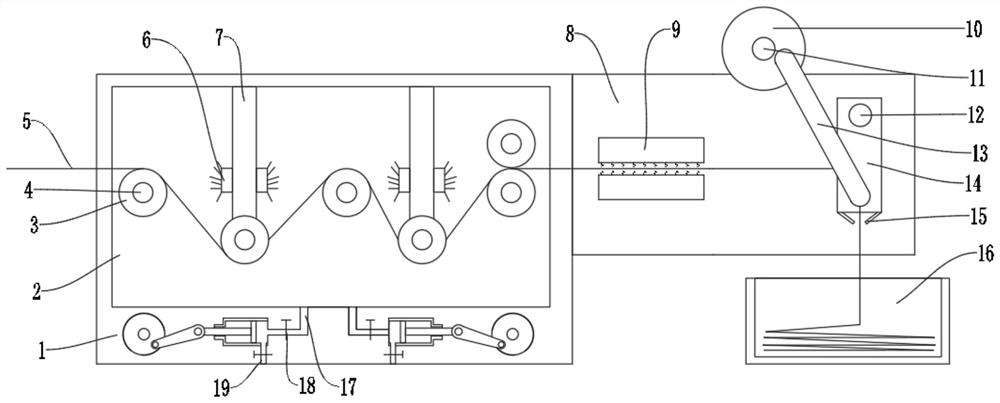
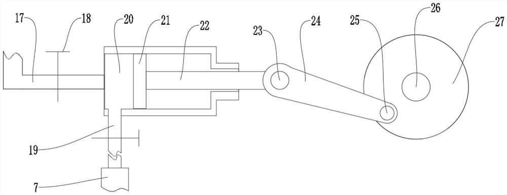
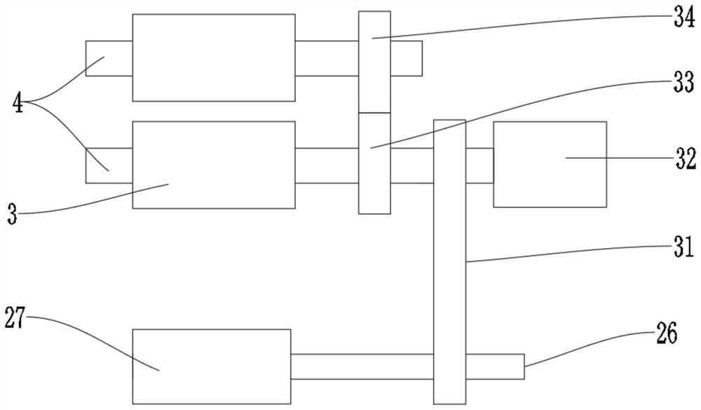
[0024] see Figure 1~5 , in one embodiment of the present invention, a kind of textile cloth dyeing equipment, comprises dyeing pool 2, and in said dyeing pool 2, a plurality of conveying mechanisms are arranged staggered up and down, and said conveying mechanism comprises transmission connecting rod 4 and transmission hub 3. The transmission hub 3 is used to transmit the cloth body 5 and is connected to the output end of the motor 32 through the transmission connecting rod 4, and the transmission connection rod 4 at the lowest position is rotationally connected to the connecting plate 29, on which the connecting plate 29 A water spray pipe 7 is installed, and a plurality of water spray heads 6 are arranged on both sides of the water spray pipe 7, and the water spray pipe 7 is connected with the dyeing pool 2 through a backflow mechanism 1, and the backflow mechanism 1 includes a water inlet pipe 17 , outlet pipe 19, piston chamber 20, sliding block 21, sliding connecting rod ...

Embodiment 2

[0030] see figure 1 , in one embodiment of the present invention, on the mounting plate 8 at the outlet of the dyeing pool 2, an ironing mechanism and a cloth-arranging mechanism are sequentially installed, and the ironing mechanism is composed of two steam The iron 9 is formed, and the air outlets of the two steam irons 9 are all arranged towards the cloth body 5 .

[0031]A kind of textile cloth dyeing equipment according to claim 5, characterized in that, the cloth arranging mechanism comprises a No. 2 eccentric wheel 10, a No. 2 eccentric wheel connecting rod 11, a swing connecting rod 12, a swing hinge rod 13, and a swing plate 14 and the cooling outlet pipe 15, the swing plate 14 is provided with a cloth wheel for conveying the cloth body 5 and the top of the swing plate 14 is rotationally connected with the mounting plate 8 through the swing connecting rod 12, and the two sides of the bottom of the swing plate 14 are also The second eccentric wheel 10 is connected to t...


PUM


Abstract

The invention discloses textile fabric dyeing equipment, and relates to the relatively large-range field. The equipment comprises a dyeing pool; a plurality of conveying mechanisms are arranged in thedyeing pool in an up-down staggered mode; each conveying mechanism comprises a transmission connecting rod and a conveying hub; the conveying hubs are used for conveying a fabric body and are connected with the output end of a motor through the transmission connecting rods; the transmission connecting rod located at the lowest position is rotationally connected with a connecting plate; a water spraying pipe is installed on the connecting plate; a plurality of water spraying heads are arranged on the two sides of the water spraying pipe; the water spraying pipe is connected with the dyeing pool through a backflow mechanism; the water inlet end and the water outlet end of a piston chamber in the backflow mechanism are connected with a water inlet pipe and a water outlet pipe respectively; the water inlet pipe is connected with the dyeing pool; and the water outlet pipe is connected with the water spraying pipe. A linkage mode is adopted; and compared with a traditional textile mode of spraying dye to a fabric and conveying the fabric, the linkage mode has the advantages that the extra power expenditure is reduced, the overall structure is optimized, and the dyeing effect is improved.

Description

technical field [0001] The invention relates to the technical field of cloth processing, in particular to a textile cloth dyeing equipment. Background technique [0002] Textile cloth is a commonly used material in decorative materials. Including chemical fiber carpets, non-woven wall coverings, linen cloth, nylon cloth, colored tape, flannel and other fabrics. Cloth plays a considerable role in decorative display; therefore, it is necessary to dye the cloth to increase the visual effect. [0003] In the current process of dyeing fabrics, the fabrics are put into the dyeing tank, and the fabrics are dyed during the process of conveying the fabrics. Such a color method will cause poor dyeing effect due to insufficient contact between the top of the fabric and the dye. question. Contents of the invention [0004] The object of the present invention is to provide a textile cloth dyeing equipment to solve the problems raised in the above-mentioned background technology. ...

Claims


Application Information

Patent Timeline
IPC IPC(8): D06B1/02D06C7/00D06C15/10
CPCD06B1/02D06C7/00D06C15/10
Inventor 熊东梅
Owner 熊东梅
Why Eureka
Try Eureka