

Building assembly with a corner profile for an insulating building system
- Summary
- Abstract
- Description
- Claims
- Application Information
AI Technical Summary
Benefits of technology
Problems solved by technology
Method used
Image

Examples
Embodiment Construction
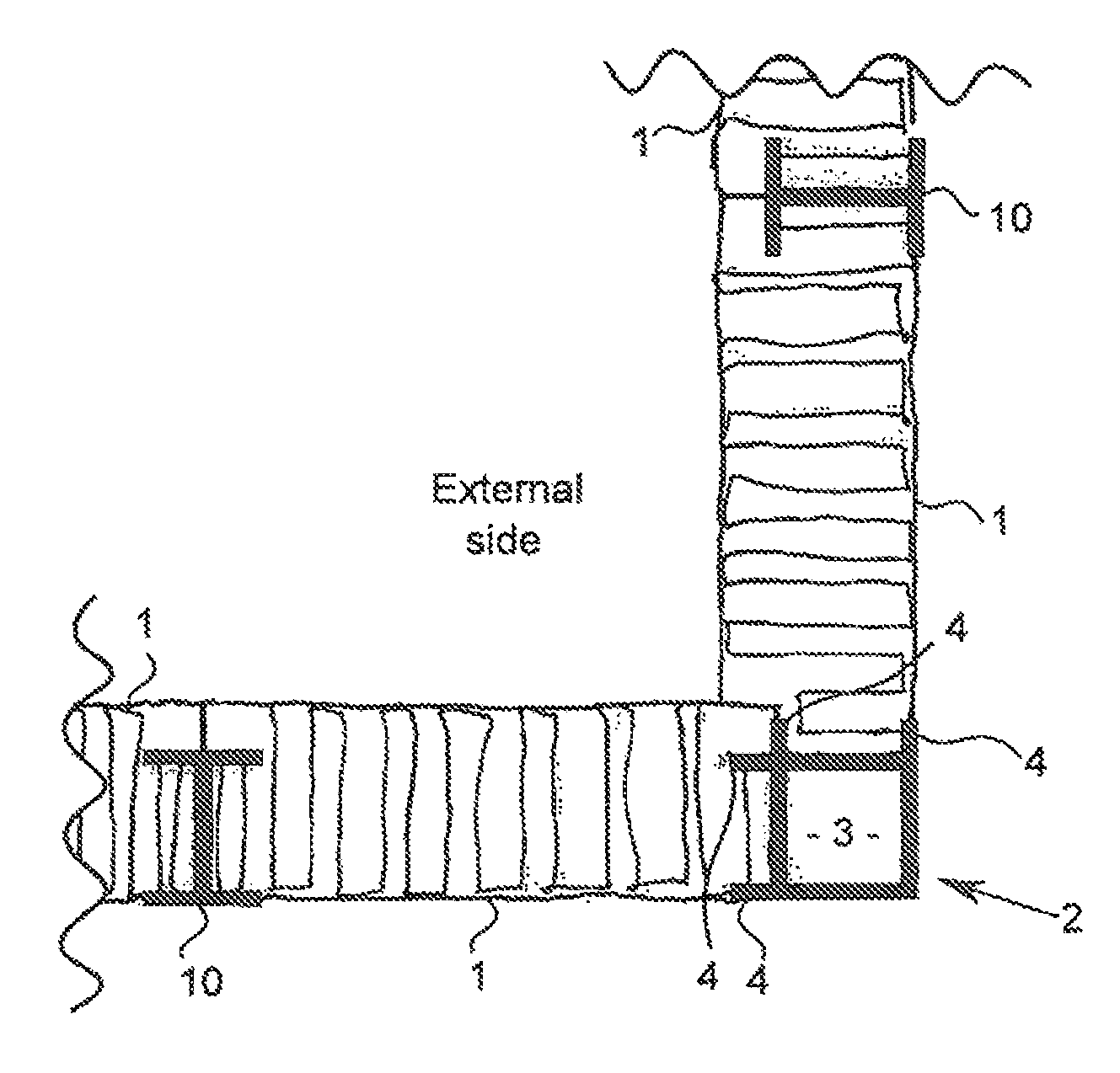
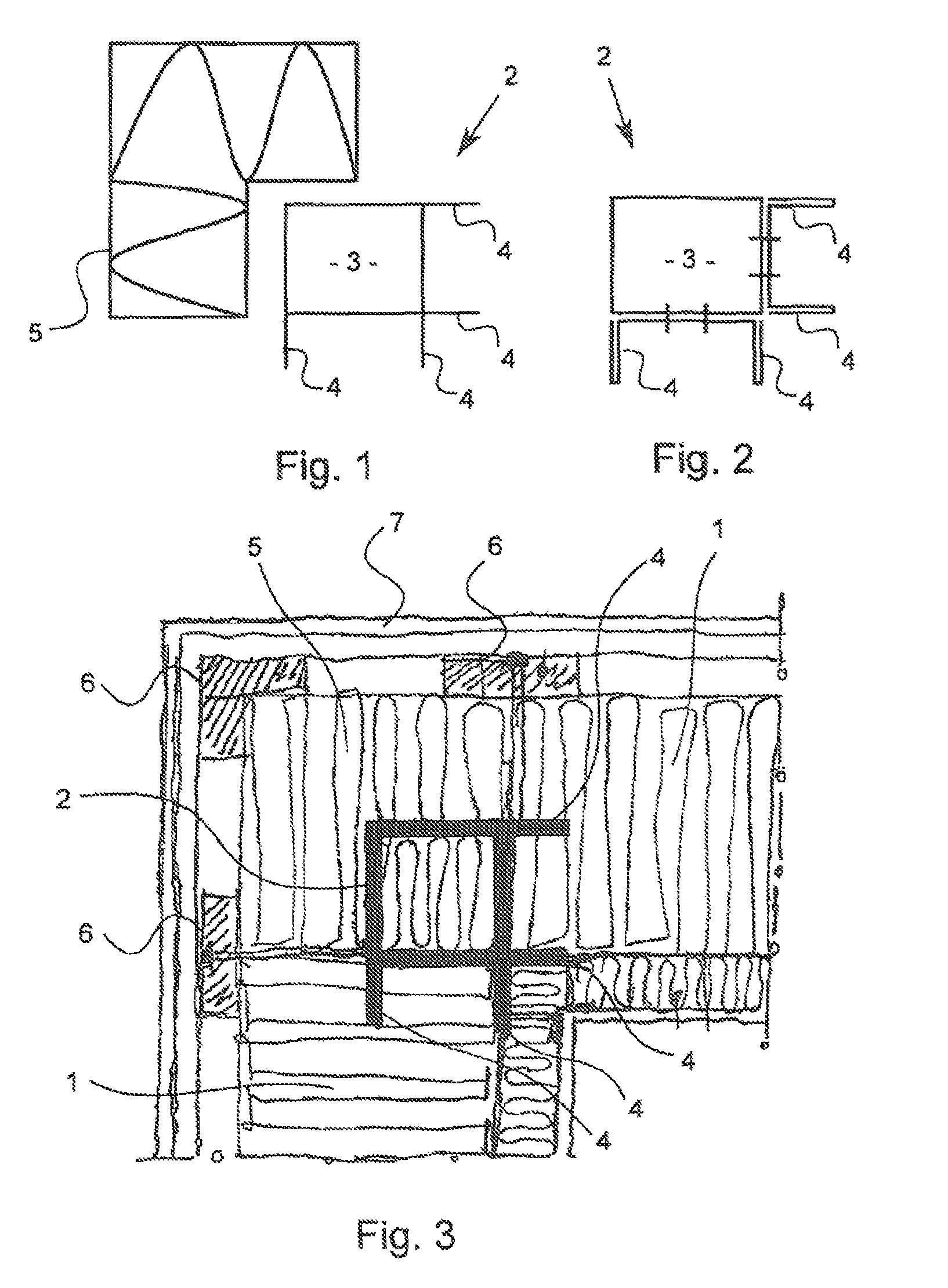
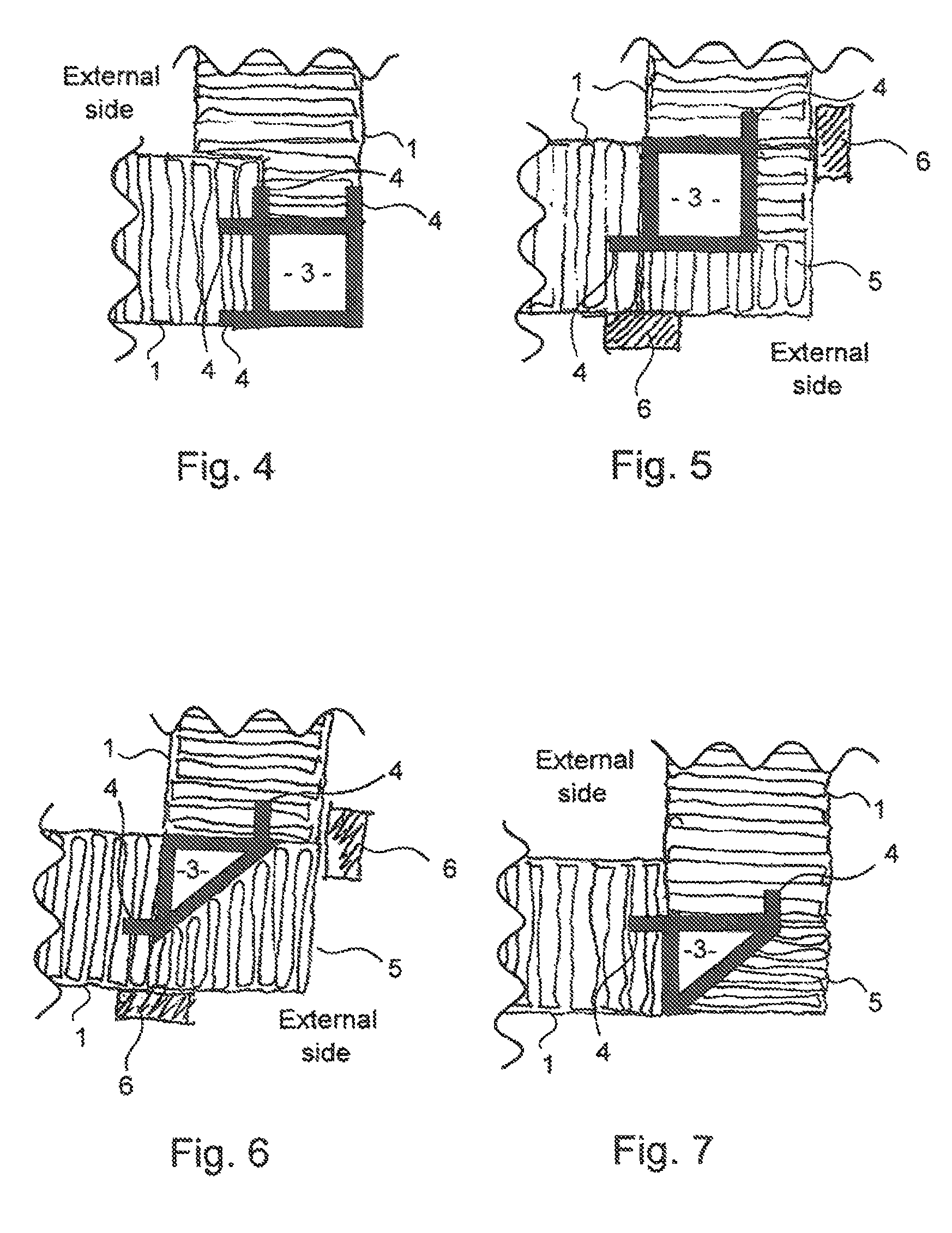
[0048]With reference to FIGS. 1-3, there is shown embodiments of a corner profile 2 with a hollow rectangular body portion 3 having four corner profile contact sides comprising flange portions 4 extending perpendicular from the body portion 3 and matching associated groove portions provided by corresponding insulation panels 1. Two or more of the flange portions 4 may be bent in one piece or otherwise formed from sheet metal and connected to the hollow body portion 3 by a suitable attachment, such as weldings, gluing or the like, cf. FIG. 2. With reference to FIG. 3, a corner profile 2 is shown with a covering insulation portion 5, for reducing thermal and acoustic bridging, and building elements 6 which may be connected to the corner profile 2. The building elements 6 may support a stiffening external cladding or bracing 7. The insulation panels 1 may have a high wool density, preferably in the range of 60-100 kg / m3, and may support the corner profile 2, by strong lateral forces, s...
PUM
 Abstract
Description
Claims
Application Information