Marine vessel

a technology for marine vessels and rotors, applied in the field of marine vessels, can solve the problems of limited use of conventional flettner rotors, no benefit of head and tail wind from flettner rotors, and no benefit in port, so as to achieve a larger cross-area of wind turbine configuration and higher output

Inactive Publication Date: 2015-02-24
WARTSILA FINLAND OY
View PDF18 Cites 4 Cited by
  • Summary
  • Abstract
  • Description
  • Claims
  • Application Information

AI Technical Summary

Benefits of technology

[0009]The basic idea of the invention is to configure the vertically arranged cylinder, i.e. the Flettner rotor, so that it provides a flexibly adaptable arrangement suitable for deployment in various operating modes of the marine vessel. The cylindrical shell of the vertically arranged cylinder comprises at least three sections with a curved portion extending between two opposite ends, whereby each of the three sections is arranged to be turnable around a respective second vertical axis. Each second vertical axis is positioned at the circumference of the cylindrical shell. Each section is arranged to be anchored into a given position. This allows for positioning the sections in various configurations suitable for a prevailing operation mode of the marine vessel.
[0015]Further, the vertically arranged cylinder advantageously comprises an internal cylindrical sleeve. By means of the internal cylindrical sleeve, an additional function can be added to the vertically arranged cylinder. The internal cylindrical sleeve can function as an exhaust pipe within the vertically arranged cylinder, whereby the various configurations discussed above can be maintained as well. This avoids having the exhaust pipe as a separate structure on the marine vessel.
[0016]Advantageously in this case, in order to provide a wind turbine, each section provided with the second vertical axis is arranged to be anchored at the internal cylindrical sleeve by means of one of its ends. This enlarges the cross-area of the wind turbine configuration thus providing a higher output.

Problems solved by technology

Such a Flettner rotor does not generate any benefit in head and tail winds.
Further, the Flettner rotor does not bring any benefit in port.
This expands the use of a conventional Flettner rotor, however, only in a limited way.

Method used


Image

  • Marine vessel
  • Marine vessel
  • Marine vessel

Examples


first embodiment

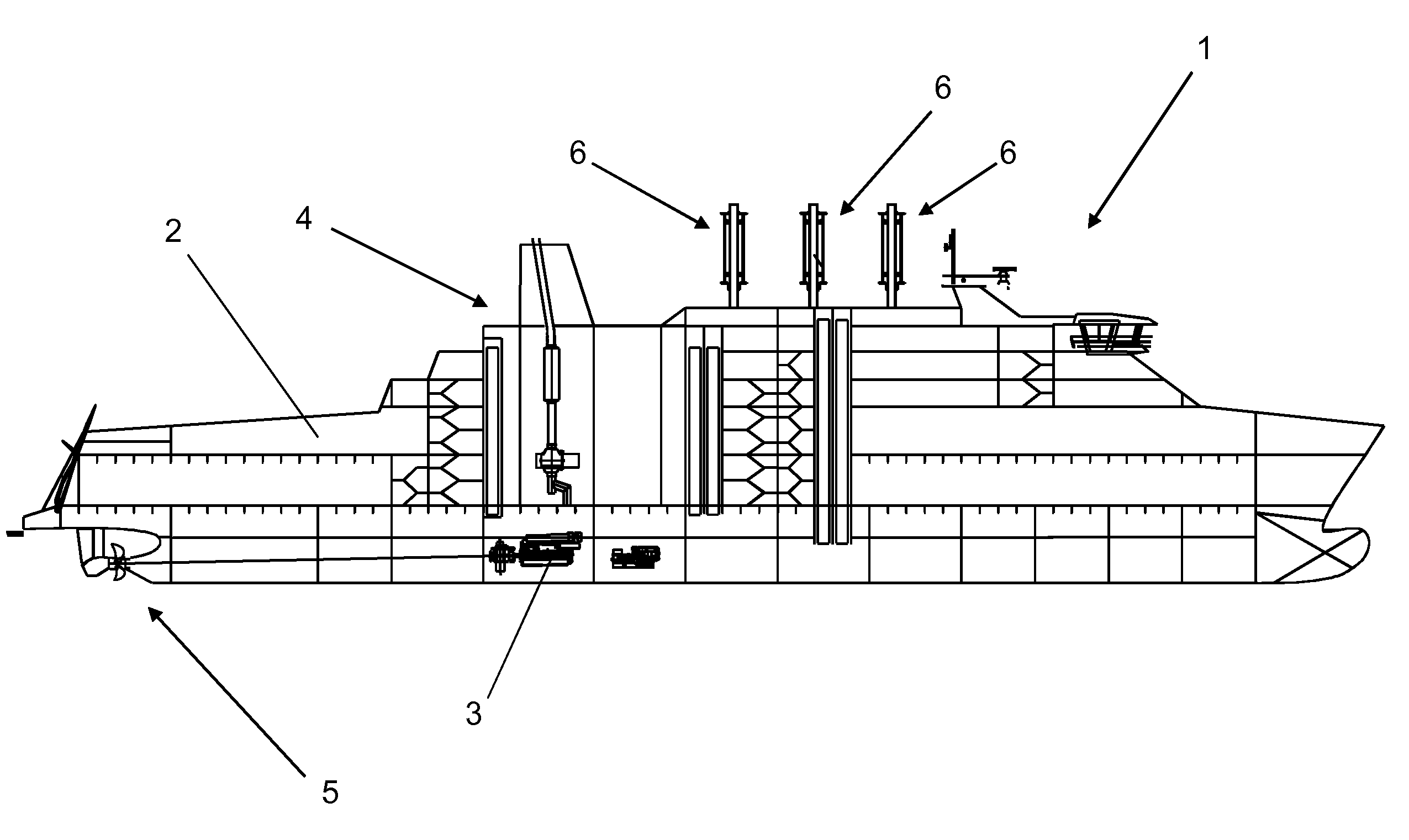
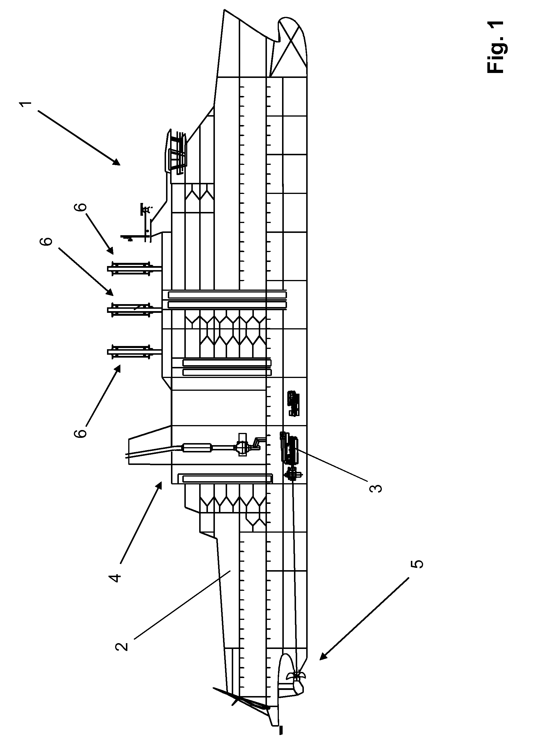
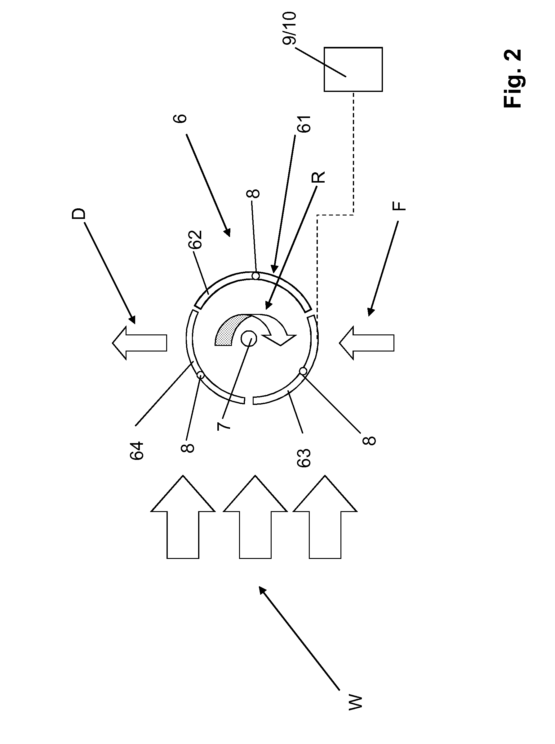
[0028]FIG. 2 illustrates the present invention in a first mode of deployment. The vertically arranged cylinder is indicated by reference sign 6 and the first vertical axis by reference sign 7. The vertically arranged cylinder 6 comprises a cylindrical shell 61 with three sections, a first section 62, a second section 63 and a third section 64. Each section forms a part, more specifically a curved portion, including two opposite ends, of the cylindrical shell 61. Further, each section is provided with a second vertical axis 8 around which the sections are turnable into a given position.

[0029]The three parallel arrows show the wind indicated by reference sign W, the curved arrow R indicates the direction of rotation of the vertically arranged cylinder 6 around the first vertical axis 7, reference sign F indicates the force, or forward thrust, generated by the Magnus effect discussed above, and reference sign D indicates the resulting direction of movement of the marine vessel (not sho...

second embodiment

[0040]FIG. 5 illustrates the present invention in a first mode of deployment. The vertically arranged cylinder is indicated by reference sign 6 and the first vertical axis by reference sign 7. The vertically arranged cylinder 6 comprises a cylindrical shell 61 with three sections, a first section 62, a second section 63 and a third section 64. Each section forms a part, more specifically a curved portion, including two opposite ends, of the cylindrical shell 61. Further, each section is provided with a second vertical axis 8 around which the sections are turnable into a given position.

[0041]The three parallel arrows show the wind indicated by reference sign W, the curved arrow R indicates the direction of rotation of the vertically arranged cylinder 6 around the first vertical axis 7, reference sign F indicates the force, or forward thrust, generated by the Magnus effect discussed above, and reference sign D indicates the resulting direction of movement of the marine vessel (not sho...


PUM


Abstract

The invention relates to a marine vessel comprising a hull and a propulsion arrangement. The marine vessel is further provided with at least one vertically arranged cylinder (6) with a cylindrical shell and with a first vertical axis (7). The vertically arranged cylinder is adapted to rotate around the first vertical axis. In order to provide a flexibly adaptable arrangement suitable for various operating modes of the marine vessel, the cylindrical shell comprises at least three sections (62, 63, 64) with a curved portion extending between two ends, whereby each of the three sections is arranged to be turnable around a respective second vertical axis (8), which is positioned at the circumference of the cylindrical shell. Each section is arranged to be anchored into a given position.

Description

TECHNICAL FIELD[0001]The present invention relates to a marine vessel comprising a hull and a propulsion arrangement including an internal combustion engine and a propulsion unit, which marine vessel further is provided with at least one vertically arranged cylinder with a cylindrical shell and with a first vertical axis, which vertically arranged cylinder is adapted to rotate around the first vertical axis according to the preamble of claim 1.BACKGROUND ART[0002]Marine vessels provided with vertically arranged revolving cylinders are previously known. A cylinder revolving in the wind will exert pressure at right angles to the wind current. This principle is known as the Magnus law or Magnus effect. Such a cylinder, or rotor, when it is spinning in the wind, generates a low pressure and a high pressure on opposite sides of the cylinder.[0003]As the wind hits a revolving / rotating cylinder from the side, one side of the cylindrical surface naturally goes against the wind, and the othe...

Claims


Application Information

Patent Timeline
Patent Type & Authority Patents(United States)
IPC IPC(8): B63B35/00B63H9/02
CPCB63H9/02Y02T70/58B63B2035/004Y02T70/5236
Inventor LEVANDER, OSKARJANSSON, MATHIAS
Owner WARTSILA FINLAND OY
Why Eureka
Try Eureka