
Self-calibrated ringing compensation for an autofocus actuator in a camera module

a technology of self-calibration and ring compensation, which is applied in the direction of camera focusing arrangement, printers, instruments, etc., can solve the problem that the settling time may not be accommodated to most, and achieve the effect of improving the autofocus rate of the camera modul

Active Publication Date: 2015-02-24
MAXIM INTEGRATED PROD INC
View PDF9 Cites 5 Cited by
  • Summary
  • Abstract
  • Description
  • Claims
  • Application Information

AI Technical Summary

Benefits of technology

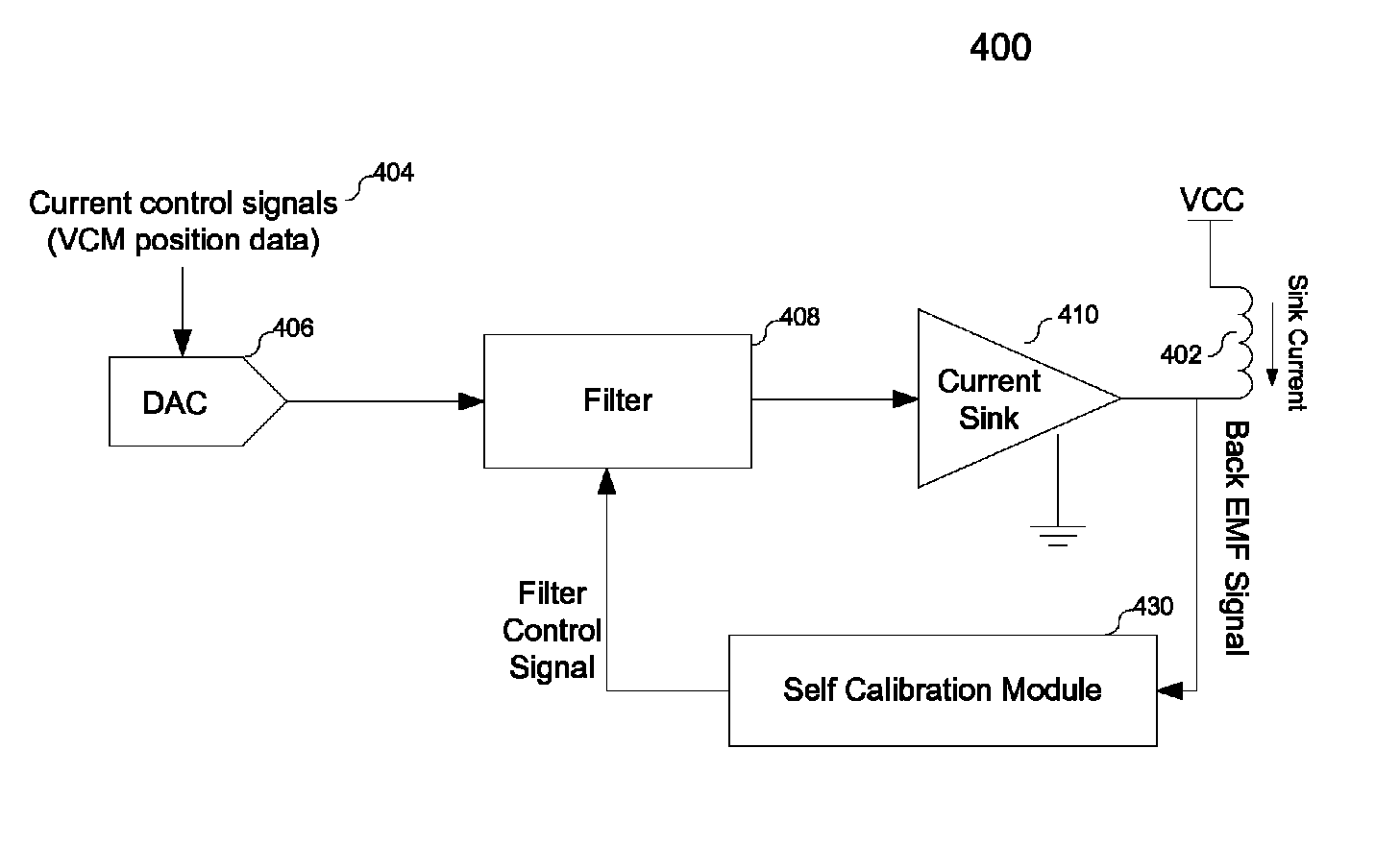
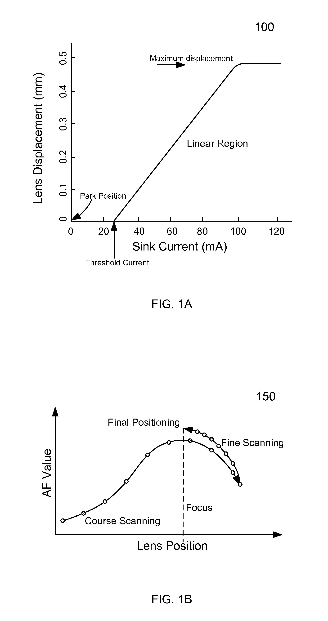
[0010]Various embodiments of the present invention relate to an actuator driver in a camera module, and more particularly to methods, systems and devices of employing self-calibrated ringing compensation to improve the autofocus rate of the camera module that is based on a voice coil motor (VCM). The free-oscillation frequency and damping coefficient of the VCM are calibrated, and used to control a sink current that drives the VCM during an autofocus.
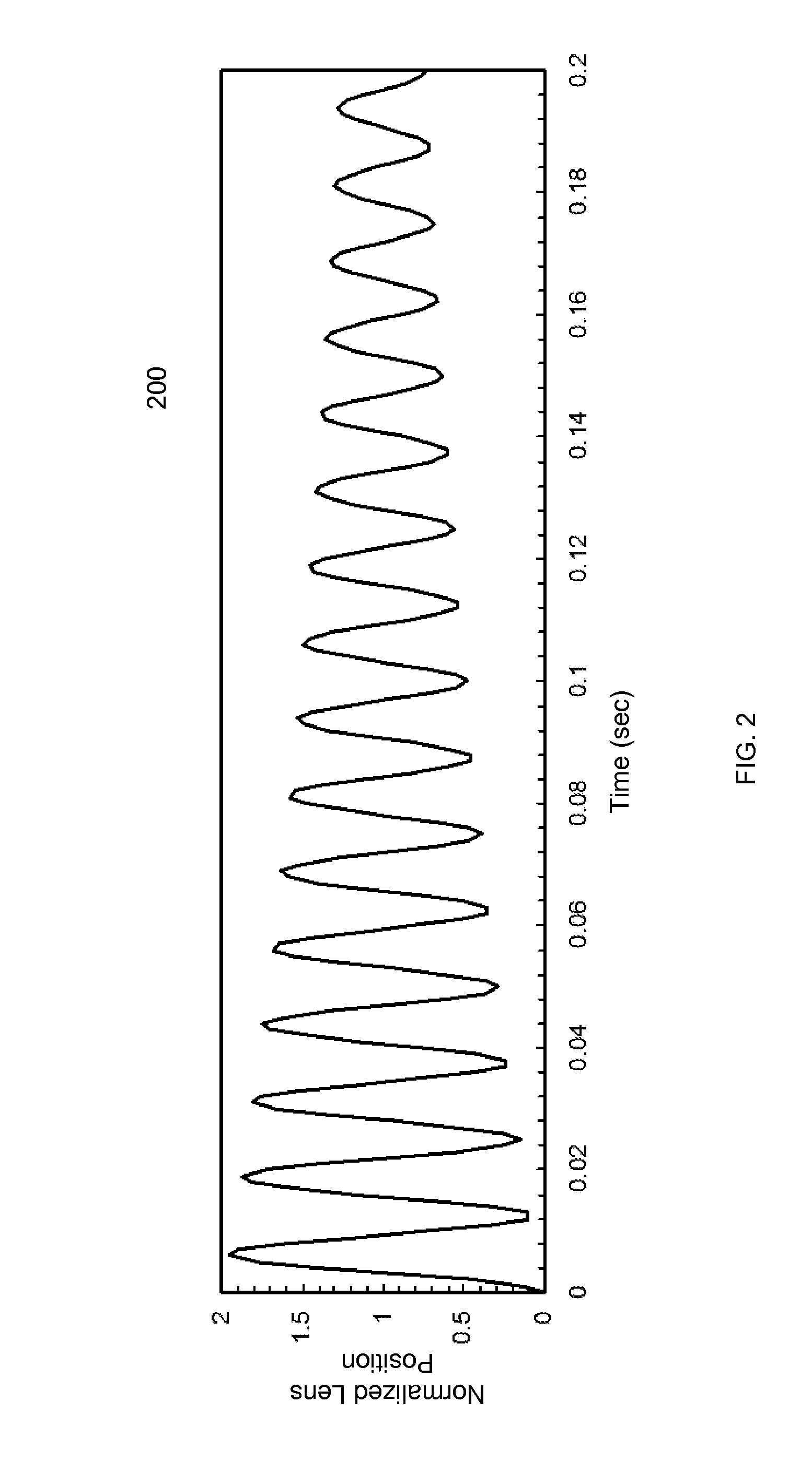
[0012]Another aspect of the invention is a self-calibrated ringing compensation method that comprises generating a sink current that induces free oscillation, measuring the free-oscillation frequency and the damping coefficient to determine a filter control signal, and configuring the VCM driver to generate a second sink current that compensates free oscillation. Such self-calibrated ringing compensation allows close tracking of free oscillation, and may efficiently enhance both the settling time of the lens and the autofocus rate of the camera module.

Problems solved by technology

This settling time may not be accommodated to most of the state-of-the-art camera modules that are capable of capturing still images and video frames at a fast autofocus rate.

Method used


Image

  • Self-calibrated ringing compensation for an autofocus actuator in a camera module
  • Self-calibrated ringing compensation for an autofocus actuator in a camera module
  • Self-calibrated ringing compensation for an autofocus actuator in a camera module

Examples


Embodiment Construction

[0028]In the following description, for purposes of explanation, specific details are set forth in order to provide an understanding of the invention. It will be apparent, however, to one skilled in the art that the invention can be practiced without these details. One skilled in the art will recognize that embodiments of the present invention, described below, may be performed in a variety of ways and using a variety of structures. Those skilled in the art will also recognize additional modifications, applications, and embodiments are within the scope thereof, as are additional fields in which the invention may provide utility. Accordingly, the embodiments described below are illustrative of specific embodiments of the invention and are meant to avoid obscuring the invention.

[0029]Reference in the specification to “one embodiment” or “an embodiment” means that a particular feature, structure, characteristic, or function described in connection with the embodiment is included in at ...


PUM


Abstract

Various embodiments of the present invention relate to an actuator driver in a camera module, and more particularly to methods, systems and devices of employing self-calibrated ringing compensation to improve the autofocus rate of the camera module that is driven by an actuator. Oscillation characteristics of the actuator are calibrated to control a sink current that drives the actuator during an autofocus. The actuator driver comprises a digital-to-analog converter (DAC), a filter, a current sink and a self calibration module. The self calibration module calibrates the free-oscillation frequency and damping coefficient, and accordingly, the DAC generates a voltage that may be subsequently bypassed, filtered or shaped by the filter. This voltage is further converted to the sink current by the current sink. Such self-calibrated ringing compensation allows close tracking of free oscillation, and may efficiently enhance the settling time of the lens and autofocus rate of the camera module.

Description

CROSS REFERENCE TO RELATED APPLICATION[0001]The application claims the benefit under 35 U.S.C. §119(e) of Provisional Application Ser. No. 61 / 502,788, entitled “Self-Calibrated Ringing Compensation for an Autofocus Actuator in a Camera Module”, filed on Jun. 29, 2011, the subject matter of which is incorporated herein by reference.BACKGROUND[0002]A. Technical Field[0003]The present invention relates generally to an actuator driver in a camera module, and more particularly to methods, systems and devices of employing self-calibrated ringing compensation to improve the autofocus convergence time of the camera module that is based on a voice coil motor (VCM) or other actuator with resonant behavior. The free-oscillation frequency and damping coefficient of the VCM are calibrated, and used to control a sink current that drives the VCM.[0004]B. Background of the Invention[0005]Camera phones have been the fast-growing consumer electronic device in the market, and miniaturized camera modul...

Claims


Application Information

Patent Timeline
Patent Type & Authority Patents(United States)
IPC IPC(8): H04N5/232G03B17/00G03B3/10
CPCH04N5/23212H04N23/67
Inventor CHRISTO, FORREST B.GALIMBERTI, ANTONIO
Owner MAXIM INTEGRATED PROD INC
Learn More