
Insulator integrated power supply

a power supply and insulation technology, applied in the direction of ac-dc conversion without reversal, emergency protection for supplying operative power, air-break switch, etc., can solve the problem of not having the power to maneuver the reclosing mechanism and close or open the breaker, and the device relying on current flow for power will not function

Active Publication Date: 2015-02-24
ABB (SCHWEIZ) AG
View PDF9 Cites 220 Cited by
  • Summary
  • Abstract
  • Description
  • Claims
  • Application Information

AI Technical Summary

Benefits of technology

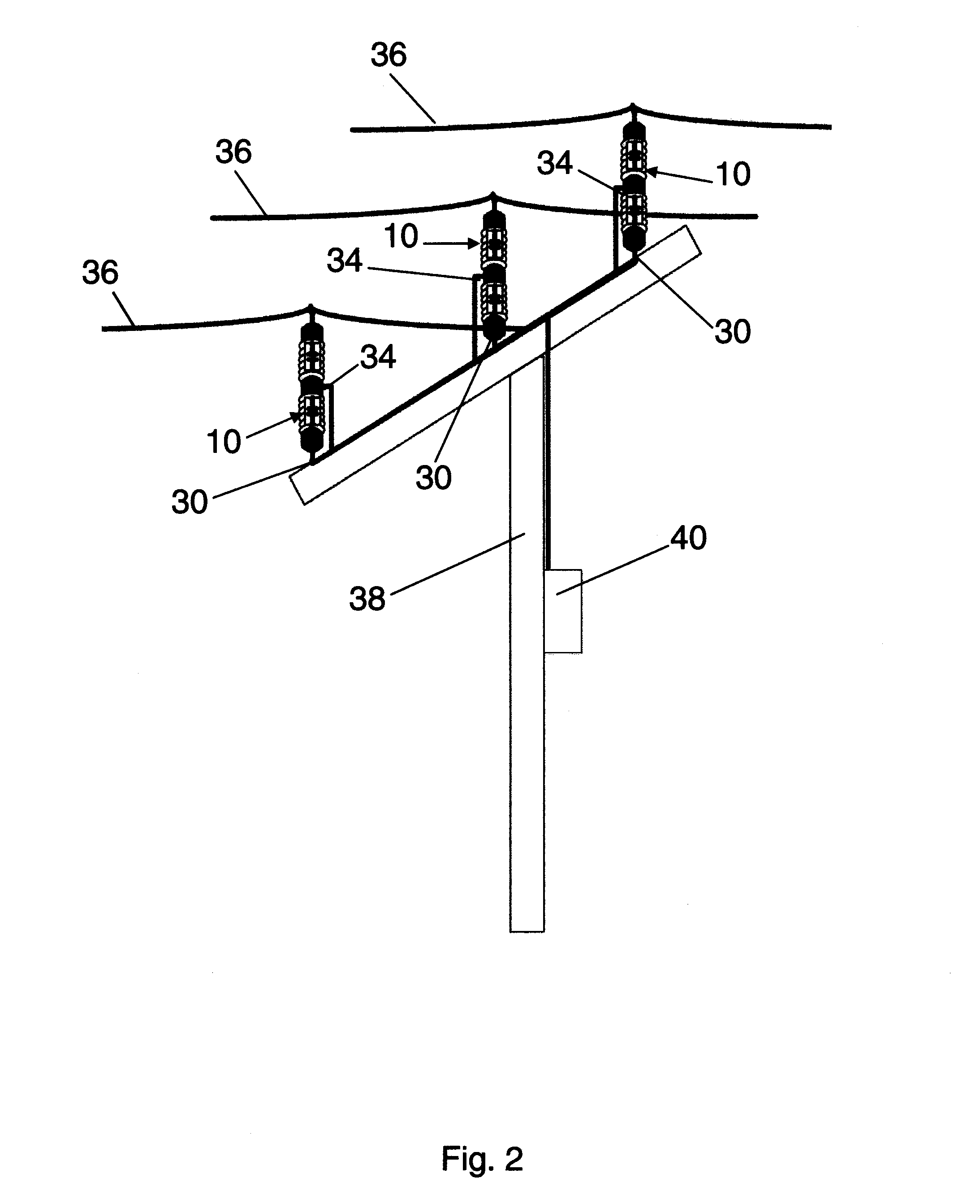
The present invention provides a power scavenging device that can be attached to an overhead power cable and a support pole. The device includes a non-conducting outer body with a first capacitor and a second capacitor connected in series at a junction. The input lead is connected to the overhead power cable, the first capacitor, and the second capacitor. The output lead is connected to the junction and the ground lead is connected to the second capacitor. A voltage source converter is connected to the output lead and the first and second capacitors form a voltage divider. The device also includes a first resistor and a second resistor connected in series at a junction. The input lead of the first resistor is connected to the first overhead power cable. The output lead of the second resistor is connected to the junction and the ground lead of the second capacitor. The voltage source converter is connected to the output leads and the first and second capacitors form a voltage divider. The device can output a regulated power supply. In addition, the invention also provides a power scavenging device that can be attached to adjacent overhead power cables.

Problems solved by technology

One major limitation of scavenging power from line currents is the elimination of that power source when a downstream fault occurs.
In the case of a recloser, for example, a fault may result in the opening of the line at that point, which in turn eliminates the flow of the current upstream of the trip.
In such a situation, any device relying on current flow for power will not function.
If, for example, a recloser relied on such a power source, it may not have the power to maneuver the reclosing mechanism and close or open the breaker.
However, batteries are relatively expensive and have a limited practical life.

Method used


Image

  • Insulator integrated power supply
  • Insulator integrated power supply
  • Insulator integrated power supply

Examples


Embodiment Construction

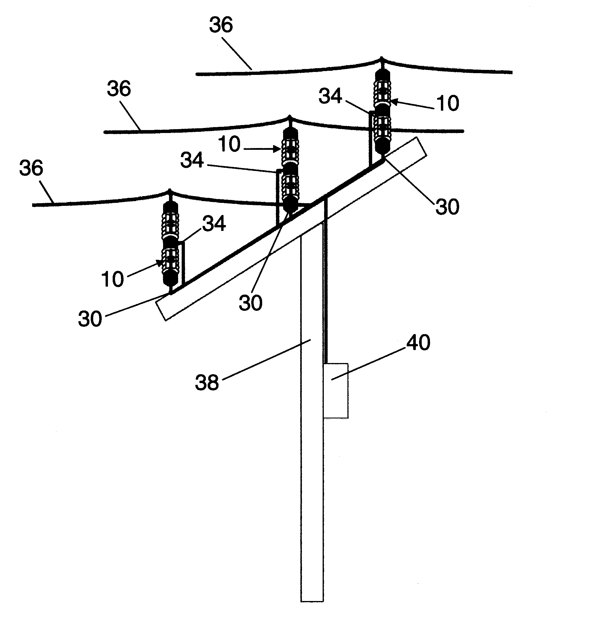
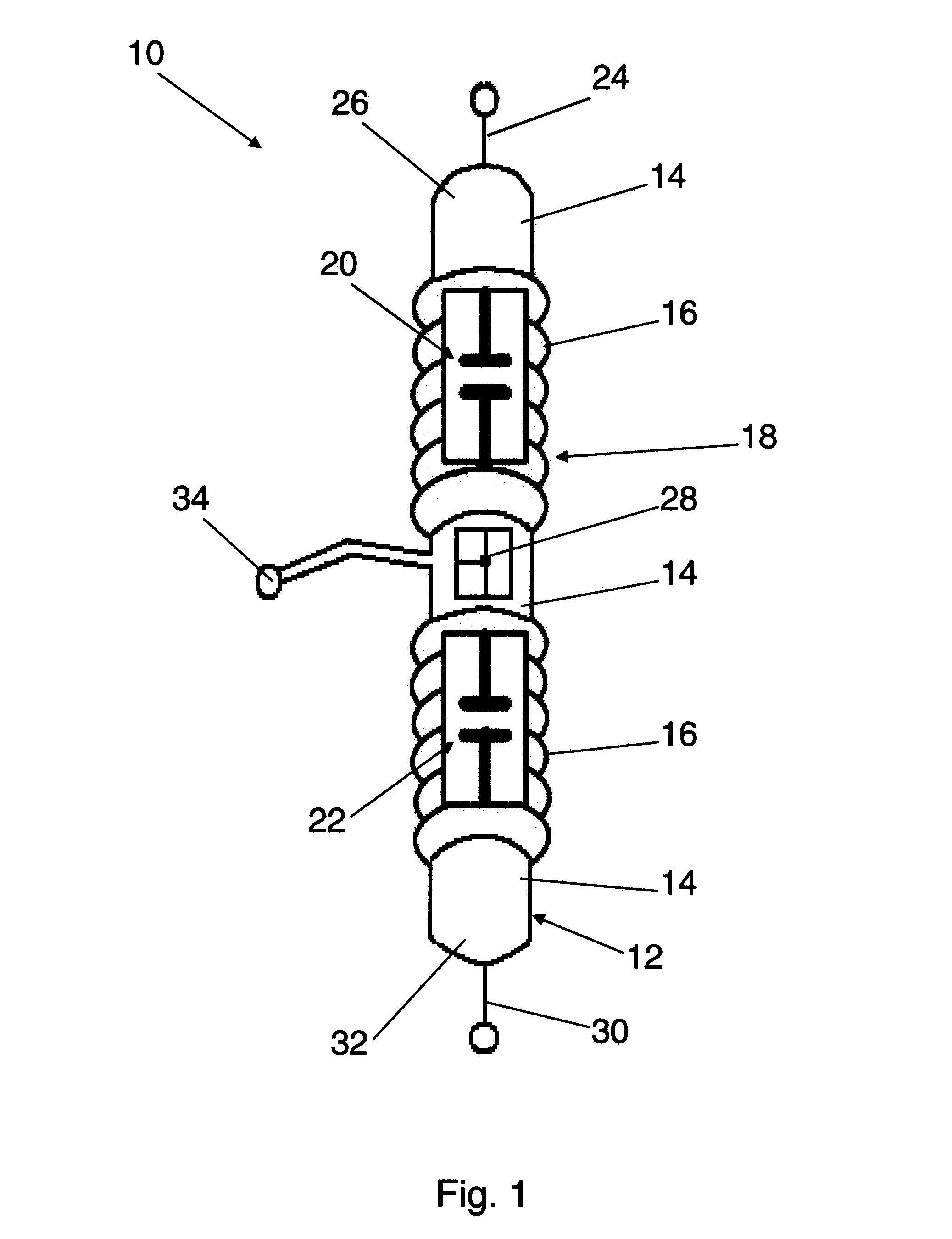
[0014]In a first embodiment of the present invention, reference is made to FIG. 1, where a device 10 is shown partially schematically. Device 10 includes a body 12 having a central cylindrical portion 14 a pair of ribbed portions 16. Body 12 is adapted to function as a non-conducting, insulating bushing. Thus, body 12 is composed of a material that is substantially non-conductive. A voltage divider 18 is positioned inside body 12. In this or other embodiments, voltage divider 18 is completely encapsulated within body 12. Voltage divider 18 includes a first capacitor 20 connected in series with a second capacitor 22. An input lead 24 is connected to the first capacitor 20 and extends outwardly from a top end 26 of body 12. First capacitor 20 is connected to second capacitor 22 at a junction 28. A ground lead 30 is connected to the second capacitor 22 and extends outwardly from a bottom end 32 of body 12. An output lead 34 is connected to junction 28 and extends outwardly from a middl...


PUM

PropertyMeasurementUnit
output voltageaaaaaaaaaa
poweraaaaaaaaaa
electrical distributionaaaaaaaaaa

Abstract

A power scavenging device attaches to an overhead power cable and a support pole. The power scavenging device includes a non-conducting outer body and a first capacitor and a second capacitor that are connected in series forming a voltage divider. A voltage source converter is electrically connected to the output of the power scavenging device. The voltage source converter outputs a regulated power.

Description

TECHNICAL FIELD[0001]The present invention relates to power supplies for electrical distribution equipment. Specifically, the present invention relates to a power supply integrated into a bushing.BACKGROUND[0002]Line currents in electric power distribution cables are commonly used to produce auxiliary power. This auxiliary power often referred to as “scavenged power,” is used to power a variety of devices used in monitoring and controlling electrical distribution.[0003]One major limitation of scavenging power from line currents is the elimination of that power source when a downstream fault occurs. In the case of a recloser, for example, a fault may result in the opening of the line at that point, which in turn eliminates the flow of the current upstream of the trip. In such a situation, any device relying on current flow for power will not function. If, for example, a recloser relied on such a power source, it may not have the power to maneuver the reclosing mechanism and close or ...

Claims


Application Information

Patent Timeline
Patent Type & Authority Patents(United States)
IPC IPC(8): H02M7/06H01B17/00H01H33/00H01H33/02H02H1/06
CPCH01H33/008H01B17/005H01H33/022H01H33/027H02H1/06
Inventor HAI-MAHARSI, MOHAMED Y.
Owner ABB (SCHWEIZ) AG
Learn More