Wireless power transmission system

a power transmission system and wired technology, applied in the field of wired power transmission units, can solve the problems of untidy appearance, he, her or it stumbles, and the portability of wired power transmission devices is much limited, and achieve the effect of efficient power transmission

Active Publication Date: 2015-03-03
PANASONIC INTELLECTUAL PROPERTY MANAGEMENT CO LTD
View PDF22 Cites 251 Cited by
  • Summary
  • Abstract
  • Description
  • Claims
  • Application Information

AI Technical Summary

Benefits of technology

[0035]In a wireless power transmission unit and system according to the present invention, power can be transmitted wirelessly to a power receiving section in a broader range. In addition, according to the present invention, power can be transmitted efficiently according to the arrangement of the power receiving section.

Problems solved by technology

However, if an electronic device is connected to an AC outlet with a wire, then the portability of that device is much limited.
On top of that, wired power transmission not just would give an untidy appearance but also could catch someone or something with the wire and make him, her or it stumble on it.

Method used


Image

  • Wireless power transmission system
  • Wireless power transmission system
  • Wireless power transmission system

Examples


embodiment 1

[0083]Hereinafter, a first preferred embodiment of a wireless power transmission unit according to the present invention will be described.

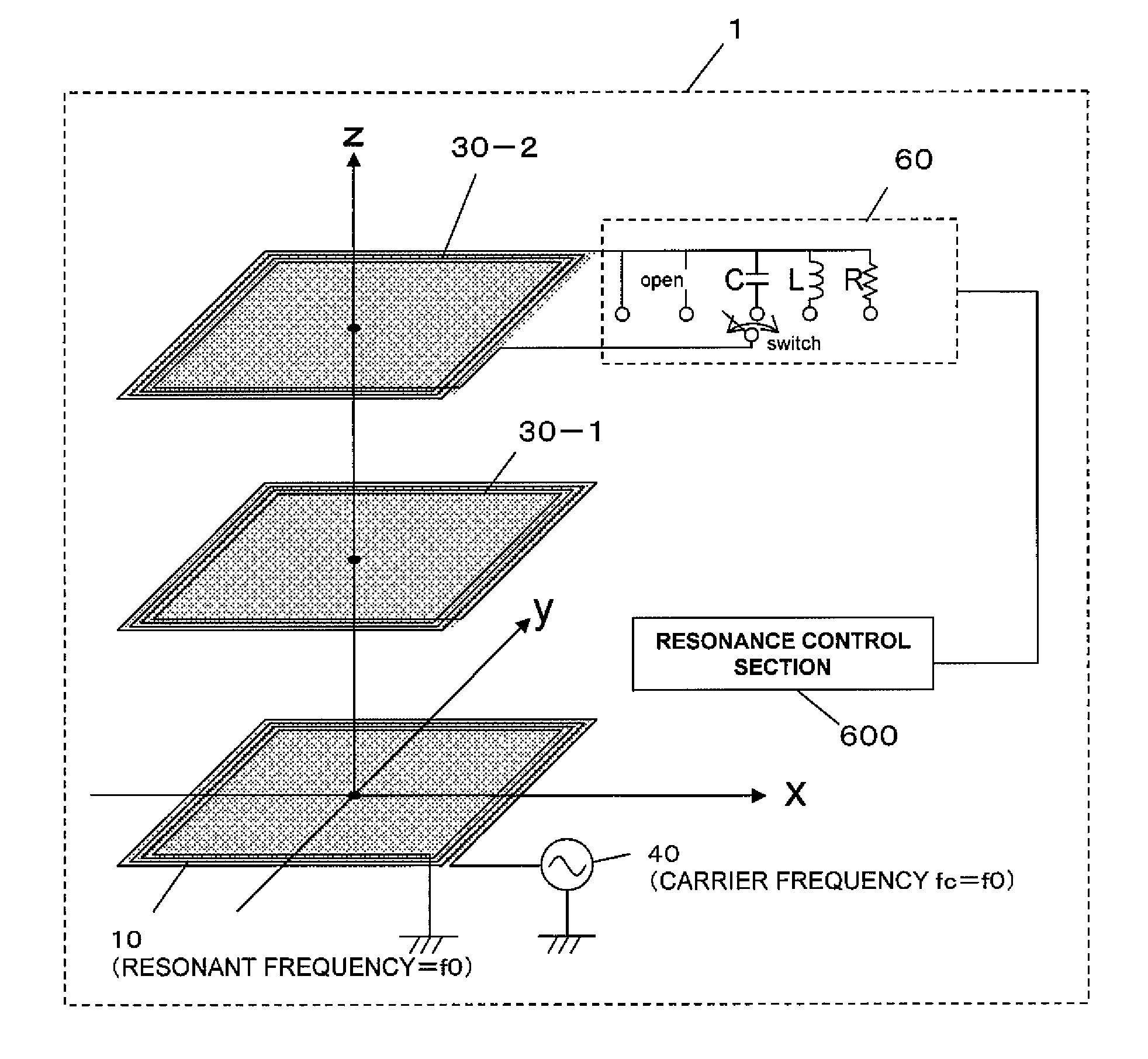
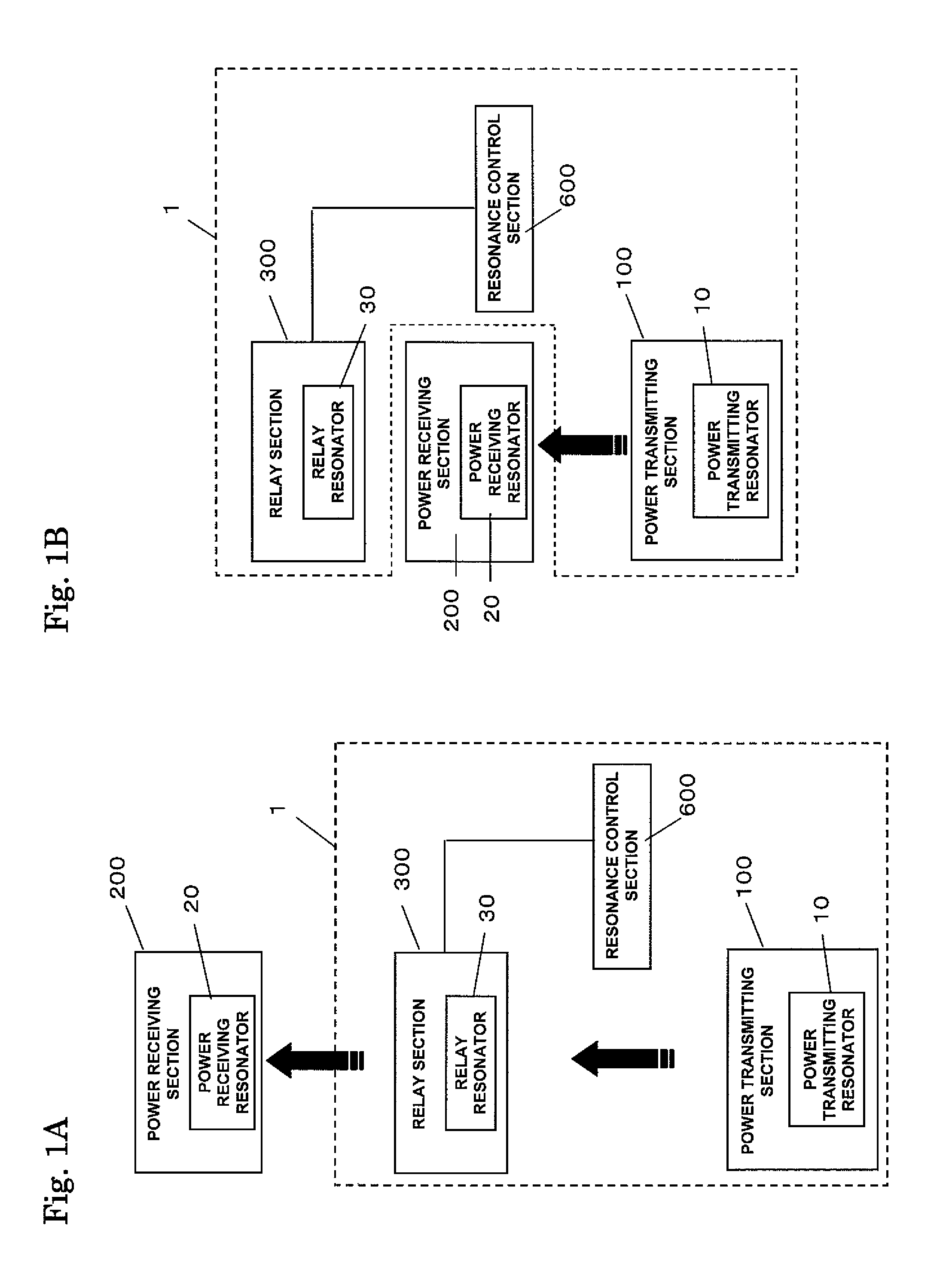
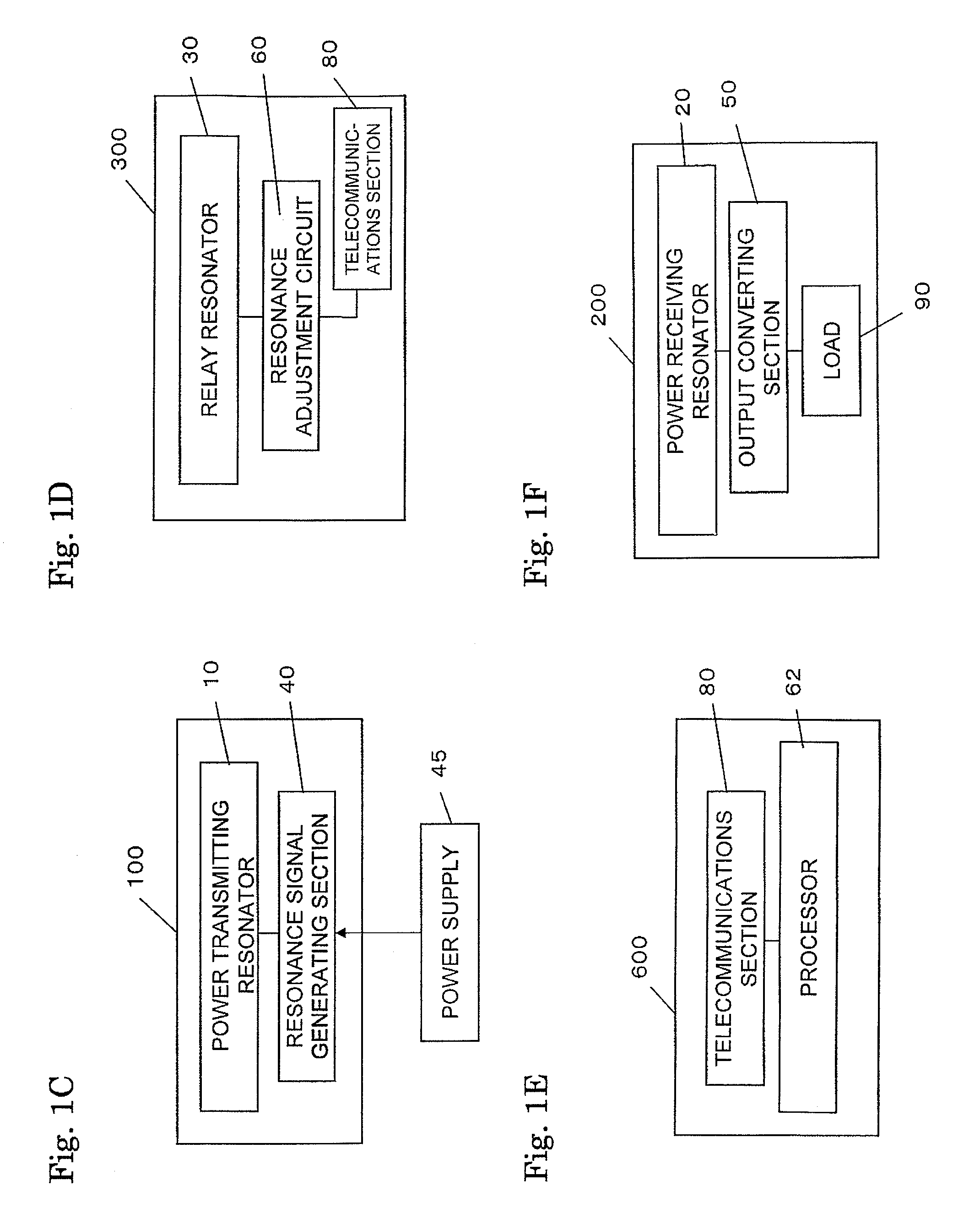
[0084]As shown in FIG. 1G, the wireless power transmission unit 1 of this preferred embodiment includes a power transmitting section 100 that resonates at a resonant frequency f0, two relay sections 300, and a resonance control section 600.

[0085]Now let's look at FIG. 2, which illustrates the relative arrangement of the power transmitting resonator 10 and the relay resonators 30 in the wireless power transmission unit 1 of this preferred embodiment. In FIG. 2, these two relay resonators 30 are identified by mutually different reference numerals 30-1 and 30-2, respectively. In this description, when respective relay resonators 30 need to be mentioned on an individual basis, those resonators are identified by mutually different reference numerals such as 30-1, 30-2, and so on. When those relay resonators need to be collectively referred to, however...

embodiment 2

[0111]Hereinafter, another preferred embodiment of a wireless power transmission system according to the present invention will be described with reference to FIG. 6, which illustrates an exemplary arrangement for a wireless power transmission unit 1 according to this second preferred embodiment.

[0112]This wireless power transmission unit 1 includes a power transmitting section 100 that resonates at a resonant frequency f0, relay sections 300 that can resonate at a selected one of multiple frequencies including that resonant frequency f0, a resonance control section 600 for controlling resonance conditions imposed on the relay sections 300, and a power receiving position detecting section 70 for detecting the position of the power receiving resonator 20. It should be noted that since the power receiving resonator 20 forms part of the power receiving section 200, an approximate position of the power receiving resonator 20 can be detected by detecting the position of the power receivi...

embodiment 3

[0148]Hereinafter, still another preferred embodiment of a wireless power transmission unit according to the present invention will be described with reference to FIG. 15. The wireless power transmission unit of this preferred embodiment includes three power transmitting resonators 10-1, 10-2, and 10-3. FIG. 15 illustrates the arrangement of these power transmitting resonators 10-1, 10-2, and 10-3 but omits illustration of relay resonators.

[0149]In the wireless power transmission unit of this preferred embodiment, the resonator planes of these three power transmitting resonators 10-1, 10-2, and 10-3 are parallel to the xy, yz and zx planes, respectively. If the power receiving resonator 20 is put in the rectangular parallelepiped space that is defined by these three power transmitting resonators 10-1, 10-2, and 10-3, power can always be transmitted from the three power transmitting resonators 10-1, 10-2, and 10-3 to the power receiving resonator 20, no matter which direction the pow...


PUM

PropertyMeasurementUnit
frequencyaaaaaaaaaa
frequencyaaaaaaaaaa
lengthaaaaaaaaaa

Abstract

A wireless power transmission unit according to the present invention transmits power wirelessly from a power transmitting section 100 to a power receiving section 200 through a resonant magnetic field. The unit includes: the power transmitting section 100, which resonates at a resonant frequency f0; at least one relay section 300, which can resonate at a frequency that is selected from multiple frequencies including the resonant frequency f0; and a resonance control section 600 that outputs information that specifies a resonance condition to be imposed on the relay section 300 according to the arrangement of the power receiving section 200 and that makes the relay section 300 resonate on the resonance condition that has been specified in accordance with that information.

Description

[0001]This application claims priority under 35 USC §119(e) to U.S. Provisional Application No. 61 / 360,978 filed on Jul. 2, 2010, the entire contents of which are incorporated herein by reference.BACKGROUND OF THE INVENTION[0002]1. Field of the Invention[0003]The present invention relates to a wireless power transmission unit that can transfer energy from a power transmitting section to a power receiving section by a non-contact method. The present invention also relates to a device including a power receiving section to be used in combination with such a wireless power transmission unit and to a wireless power transmission system.[0004]2. Description of the Related Art[0005]Currently, power is supplied to various electronic devices ordinarily via wires (or cables). Such a wired power supply is advantageous in terms of power supply stability and safety precautions against electric shock because electric power is supplied while being confined in the wire. However, if an electronic de...

Claims


Application Information

Patent Timeline
Patent Type & Authority Patents(United States)
IPC IPC(8): H01F27/42H02J5/00H02J7/02
CPCH02J5/005H02J7/025H02J7/00045H02J50/502H02J50/90H02J50/12
Inventor SADA, TOMOKAZUKANNO, HIROSHI
Owner PANASONIC INTELLECTUAL PROPERTY MANAGEMENT CO LTD
Why Eureka
Try Eureka