Connecting fitting, frame provided with same, and building using frame

a technology of connecting fittings and fittings, which is applied in the direction of rod connections, mechanical devices, fastening means, etc., can solve the problems of c-shaped gap between flanges, flanges cannot be supported from the inside by section-steel jointing fittings, and obstacles to the c-shaped gap

Active Publication Date: 2015-03-10
NIPPON STEEL CORP +1
View PDF38 Cites 15 Cited by
  • Summary
  • Abstract
  • Description
  • Claims
  • Application Information

AI Technical Summary

Benefits of technology

[0010]It is an object of the present invention to provide is a connecting fitting that, by passing between both lips of a C-section steel, can be attached between two flanges in such a manner that the C-section steel can be reinforced, to provide a frame that comprises the connecting fitting, and to provide a building that utilizes the frame.
[0014]The present invention can provide a connecting fitting that, by passing between both lips of a C-section steel, can be attached between two flanges in such a manner that the C-section steel can be reinforced, provide a frame that comprises the connecting fitting, and provide a building that utilizes the frame.

Problems solved by technology

Accordingly, the lips constitute an obstacle upon attempting to attach the section-steel jointing fitting by passing the section-steel jointing between the lips of the C-section steel.
Doing so, however, gives rise to a gap between both flanges of the C-section steel and the section-steel jointing fitting, whereby the flanges can no longer be supported from the inside by the section-steel jointing fitting.
The reinforcement effect of the C-section steel that is elicited by the section-steel jointing fitting becomes weaker as a result.

Method used


Image

  • Connecting fitting, frame provided with same, and building using frame
  • Connecting fitting, frame provided with same, and building using frame
  • Connecting fitting, frame provided with same, and building using frame

Examples


Embodiment Construction

[0022]Embodiments of the present invention are explained next with reference to accompanying drawings. However, the embodiments below are examples in which the present invention is embodied, and are not meant to limit the technical scope of the invention in any way.

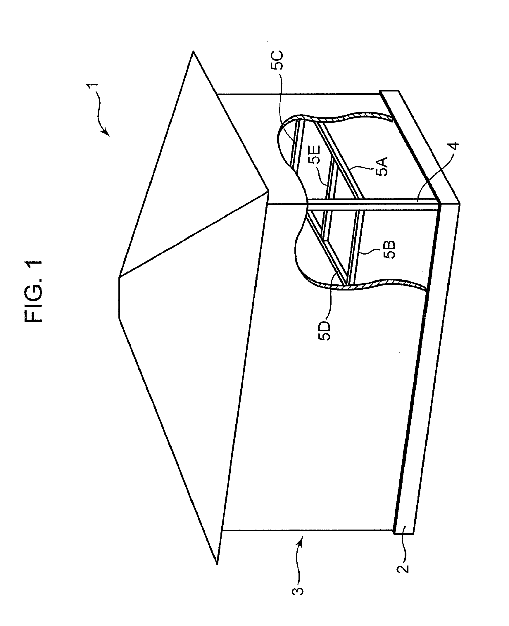
[0023]FIG. 1 is a perspective-view diagram illustrating a house according to an embodiment of the present invention.

[0024]With reference to FIG. 1, a house 1, as an example of a building, comprises a foundation 2 and a house body 3 that is provided on the foundation 2.

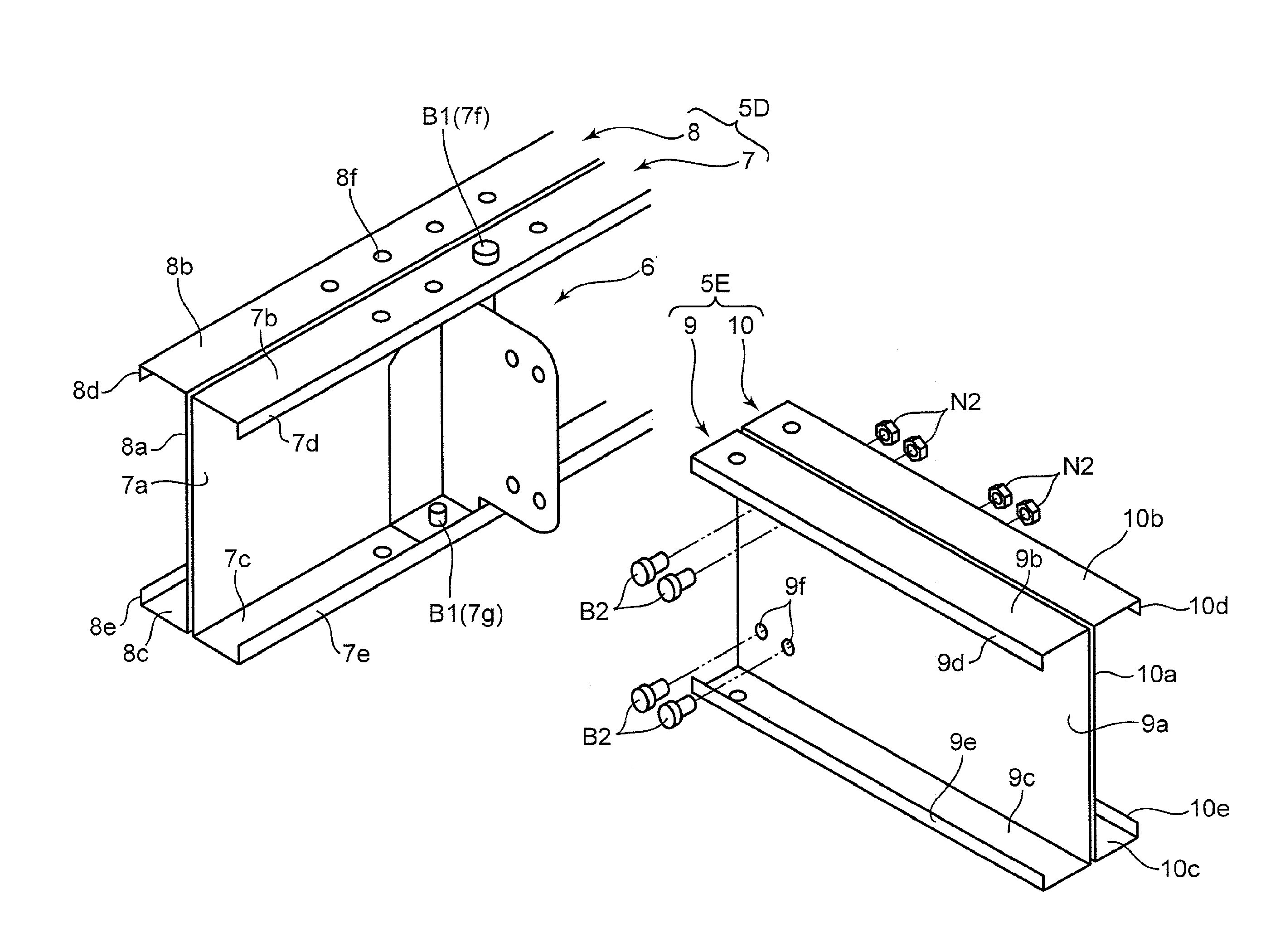
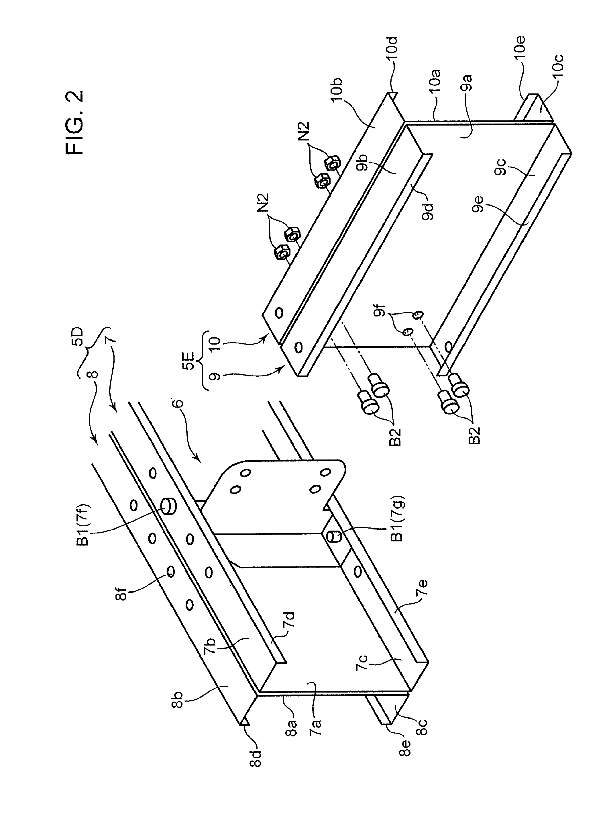
[0025]The house body 3 comprises a plurality of pillars 4 (FIG. 1 illustrates one pillar 4) that are stood on the foundation 2, a plurality of beams 5A to 5E that are joined to the pillars 4 in the horizontal direction, and connecting fittings 6 (FIG. 2) for connecting the beams 5A to 5E to each other.

[0026]The plurality of beams 5A to 5E is for instance as follows. The beams 5A to 5C are provided between two pillars 4. The beam 5D has a first end joined to ...


PUM


Abstract

The connecting fitting comprises a band-like section 14 and a back plate 11 that can be inserted between the flanges 7b, 7c by passing between lips 7d, 7e, in an insertion attitude, and a joining section 15 that can join a beam 5E in a state where the band-like section 14 and the back plate 11 are inserted between the flanges 7b, 7c. The band-like section 14 has a pair of abutting sections 14b, 14c that can abut respective inner surfaces of both flanges 7b, 7c of a C-section steel 7, in an attachment attitude resulting from rotation from the insertion attitude by a predetermined angle.

Description

TECHNICAL FIELD[0001]The present invention relates to a frame that is used in buildings (for instance, houses).BACKGROUND ART[0002]Conventionally known frames that are used in buildings include, for instance, the building frame for steel-structure housing disclosed in Patent Document 1.[0003]The building frame disclosed in Patent Document 1 comprises a first H-section steel, a second H-section steel that is joined to an opening of a groove of the first H-section steel, in a state where a leading end section of the second H-section steel is butting against the first H-section steel, and a section-steel jointing fitting for joining the second H-section steel to the first H-section steel.[0004]The first H-section steel has a web and a pair of flanges that flank the web from above and below. The section-steel jointing fitting fits between both flanges in such a way so as to come into close contact with both flanges of the first H-section steel. Through fitting of the section-steel joint...

Claims


Application Information

Patent Timeline
Patent Type & Authority Patents(United States)
IPC IPC(8): E04C2/38E04B1/24E04B1/41
CPCE04B1/40E04B1/2403E04B2001/2415E04B2001/2448E04B2001/2457E04B2001/2472F16B2200/506F16B2200/503F16B7/00E04B1/388
Inventor SUGIHARA, MASAMISUNAGAWA, HITOMIHATAE, TOMOYAOGAWA, MASAYUKIKAWAKAMI, HIROAKIFUJIHASHI, KAZUNORI
Owner NIPPON STEEL CORP
Why Eureka
Try Eureka