C-shaped profile and partition comprising a C-shaped profile

A profile and side technology, applied in the field of C-profiles, can solve the problems of not increasing, increasing manufacturing costs, etc.

Inactive Publication Date: 2008-03-26
RICHTER SYST
View PDF1 Cites 2 Cited by
  • Summary
  • Abstract
  • Description
  • Claims
  • Application Information

AI Technical Summary

Problems solved by technology

At the same time, it should not increase or incr

Method used


Image

  • C-shaped profile and partition comprising a C-shaped profile
  • C-shaped profile and partition comprising a C-shaped profile
  • C-shaped profile and partition comprising a C-shaped profile

Examples


Embodiment Construction

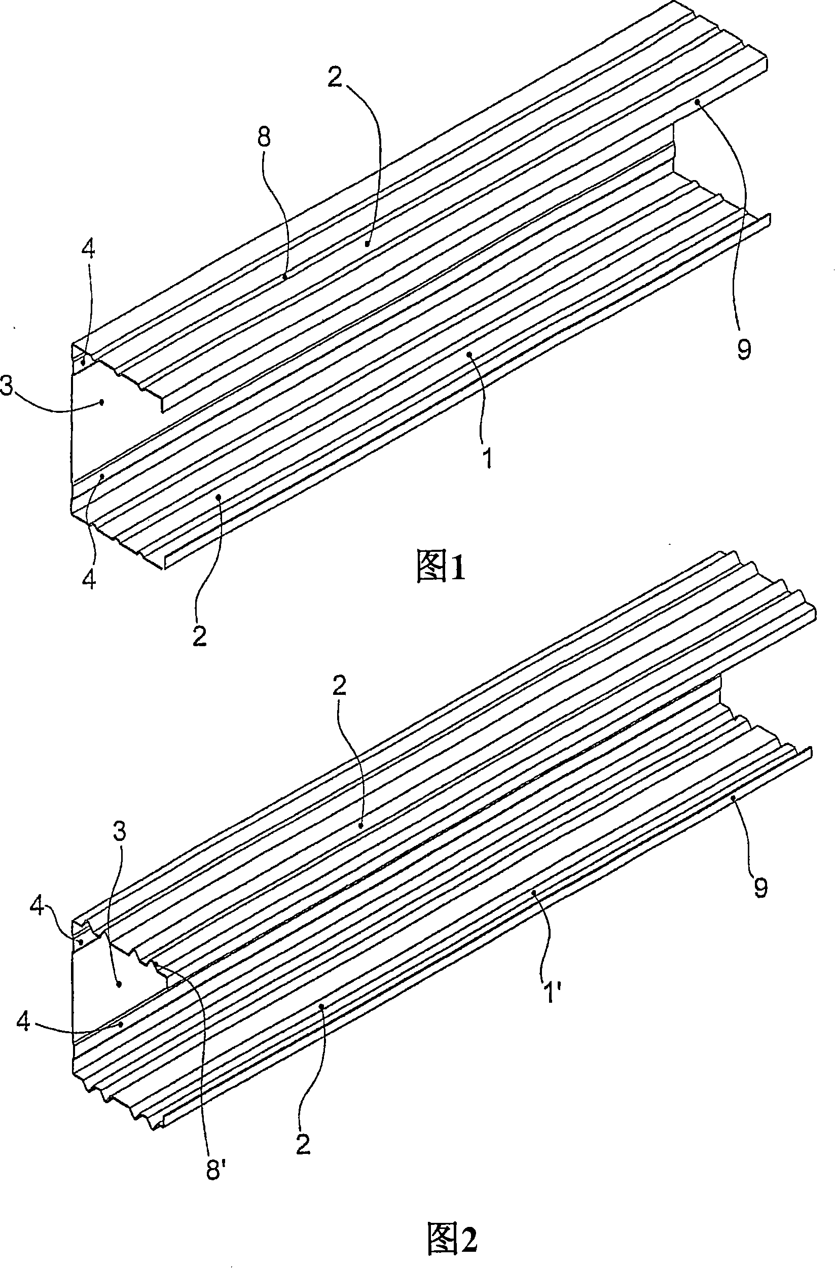
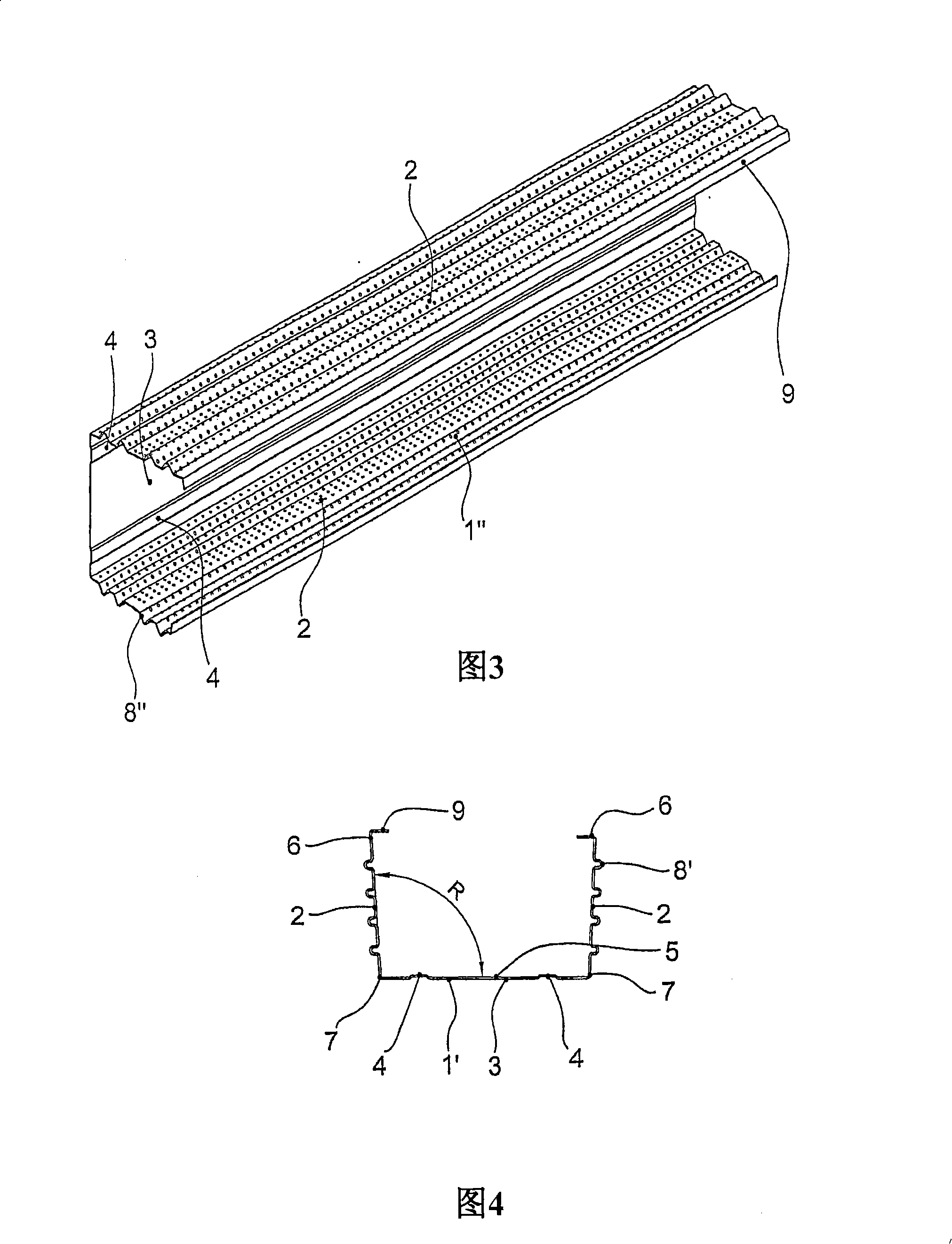
[0027] The figures show different embodiments of C-profiles 1 , 1 ′, 1 ″ made of sheet metal for partition walls covered on both sides. Each C-profile 1 , 1 ′, 1 ″ has two Sides 2 and a bottom 3 .

[0028] The base 3 is formed substantially flat. In the embodiment shown in FIGS. 1 to 3 , grooves 4 are provided on both sides in the outer region of the base 3 , which extend in the longitudinal direction of the C-profile 1 , 1 ′, 1 ″. The base 3 There may be openings, recesses or perforations not shown. The C-profiles 1 , 1 ′, 1 ″ here have an elongated shape. This also applies to bottom 3. Furthermore, the bottom 3 can also have a different form than that shown.

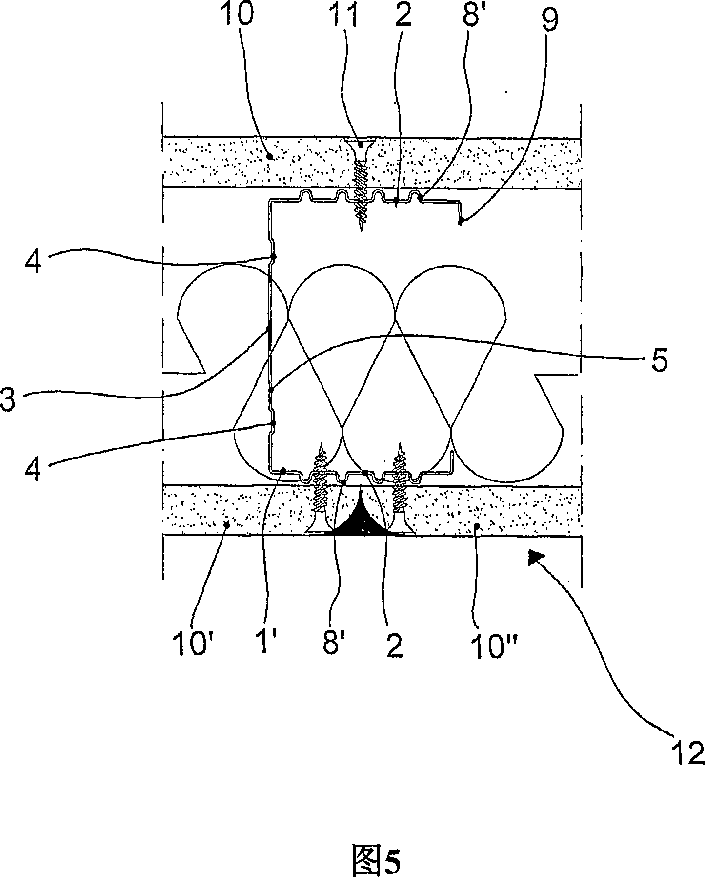
[0029] A side part 2 is arranged on each longitudinal side of the base 3 . As can be seen especially in FIG. 4 , the side 2 forms an opening angle R of greater than 90° with the bottom 3 in the unloaded state of the C-profile 1 , 1 ′, 1 ″. On the side facing the bottom 3 The opening angle R measured between the in...


PUM

PropertyMeasurementUnit
Thicknessaaaaaaaaaa

Abstract

The present invention relates to a C-section bar (1, 1' and 1'') which is made of metal plate and a wall partition that is used to be covered at the two sides, and the section bar is provided with two side parts (2) and a base part (3) connected with the side parts (2). The invention is characterized in that the base part (3) synthesizes an angular aperture (R) larger than 90 degrees to at least one side part (2) in the no-load state of the C-section bar (1, 1' and 1'').

Description

technical field [0001] The invention relates to a C-profile made of sheet metal for partition walls covered on both sides, the profile having two sides and a bottom connecting the sides. Background technique [0002] Such C-profiles are disclosed, for example, in DE 100 13 991 C1. It is commonly used in the field of interior finishing to create walls in drywall. Therein, in known C-profiles, the sides are positioned perpendicular to the bottom. [0003] While good sound insulation qualities can be obtained while using such known C-profiles to form drywall, it is nevertheless desirable to further improve the sound insulation properties. At the same time, the manufacturing cost should not be increased or should be increased in as small a range as possible. Contents of the invention [0004] It is therefore the object of the present invention to further develop a C-profile of the type mentioned at the outset in such a way that the sound insulation quality is improved, in p...

Claims


Application Information

Patent Timeline
IPC IPC(8): E04B2/74
CPCE04B2/7412
Inventor 阿尔方斯·吉恩·克瑙夫
Owner RICHTER SYST
Why Eureka
Try Eureka