
A spliced ​​bottom beam track that prevents deformation from light and temperature difference

An anti-light and bottom beam technology, which is applied to the suspension device of the wing fan, door/window accessories, gate/door, etc., can solve the problems that the large-span door body cannot be opened and closed normally, the bottom beam is bent and deformed, and the failure rate is high. Achieve the effect of avoiding thermal deformation, easy installation, maintenance and replacement, and high structural strength

Active Publication Date: 2016-12-07
张家港集优特防护设施有限公司
View PDF7 Cites 1 Cited by
  • Summary
  • Abstract
  • Description
  • Claims
  • Application Information

AI Technical Summary

Problems solved by technology

In the process of actual use, when the steel structure beam receives sunlight radiation, there will be a temperature difference between the sunny side and the shaded side. In high latitude and high altitude areas, the temperature difference is even greater. The span door body cannot be opened and closed normally, and the overall bottom beam structure has a high failure rate after thermal deformation and is difficult to maintain

Method used


Image

  • A spliced ​​bottom beam track that prevents deformation from light and temperature difference
  • A spliced ​​bottom beam track that prevents deformation from light and temperature difference
  • A spliced ​​bottom beam track that prevents deformation from light and temperature difference

Examples


Embodiment Construction

[0016] The following will clearly and completely describe the technical solutions in the embodiments of the present invention. Obviously, the described embodiments are only some of the embodiments of the present invention, rather than all the embodiments. Based on the embodiments of the present invention, all other embodiments obtained by persons of ordinary skill in the art without making creative efforts belong to the protection scope of the present invention.

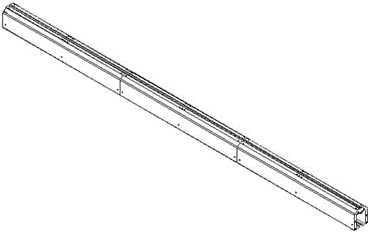
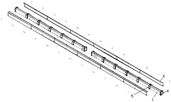
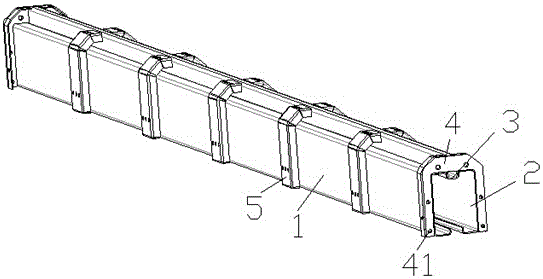
[0017] see Figure 1 to Figure 4 , the embodiment of the present invention includes:

[0018] A spliced ​​bottom beam track that prevents light and temperature difference deformation, comprising: a first C-shaped steel 1, a second C-shaped steel 2 and a rectangular steel pipe 3, and the first C-shaped steel 1 and the second C-shaped steel 2 are symmetrically arranged on the rectangular steel pipe 3 On both sides, the outer sides of the first C-shaped steel 1 and the second C-shaped steel 2 are respectively covered w...


PUM


Abstract

The invention discloses a spliced ​​bottom beam track for preventing deformation due to light temperature difference, comprising: a first C-shaped steel, a second C-shaped steel and a rectangular steel pipe, the outer sides of the first C-shaped steel and the second C-shaped steel are respectively covered with C-shaped For the protective cover, several reinforcing ribs are provided between the outer sides of the first C-shaped steel and the second C-shaped steel and the C-shaped protective cover, and the ends of the first C-shaped steel and the second C-shaped steel are provided with tabs to The bottom beam is spliced, and threaded mounting holes are respectively arranged on the first straight channel steel and the second straight channel steel. Through the above method, the jointed bottom beam rail of the present invention that prevents deformation due to light temperature difference has high structural strength, good ventilation and heat dissipation, avoids thermal deformation of the first C-shaped steel and the second C-shaped steel, and adopts a spliced ​​structure, which is convenient Installation and maintenance replacement, reducing installation and post-use costs.

Description

technical field [0001] The invention relates to the field of translational cantilever gates for perimeter entrances and exits, in particular to a spliced ​​bottom beam track that prevents deformation due to light and temperature differences. Background technique [0002] The traditional electric gates at the entrance and exit of the perimeter are split or electric telescopic gates, which have high requirements on the ground and tend to be gradually eliminated. However, the translational cantilever gate products have been well received by users for their superior ground adaptability and integrity. unanimous approval. The core part of the translational cantilever gate is the gate bottom beam, which provides a strong rigid foundation for the entire gate body, so that the gate can be suspended in the air, and at the same time constitutes a pulley track, so that the gate moves on the fixed pulley to reach the opening and closing cycle. The purpose of border entrance and exit. ...

Claims


Application Information

Patent Timeline
Patent Type & Authority Patents(China)
IPC IPC(8): E05D13/00E06B11/02
Inventor 吴东平郑健李士超
Owner 张家港集优特防护设施有限公司
Learn More