Torsion beam welding assembly structure

An assembly structure, torsion beam technology, applied in interconnection systems, suspensions, transportation and packaging, etc., can solve the problems of inability to increase torsion bars, difficult to ensure welding quality, and difficult to roll stiffness, etc., to achieve robot welding, Easy robot welding, the effect of reducing the number of welds

Pending Publication Date: 2018-05-04
IAT AUTOMOBILE TECH
View PDF0 Cites 1 Cited by
  • Summary
  • Abstract
  • Description
  • Claims
  • Application Information

AI Technical Summary

Problems solved by technology

[0003] 1) The beam and the longitudinal arm are welded, which is prone to stress concentration areas;
[0004] 2) The edge of the open beam is prone to stress concentration due to manufacturing defects, reducing fatigue life;
[0005] 3) The internal high-pressure formed

Method used


Image

  • Torsion beam welding assembly structure
  • Torsion beam welding assembly structure
  • Torsion beam welding assembly structure

Examples


Embodiment 1

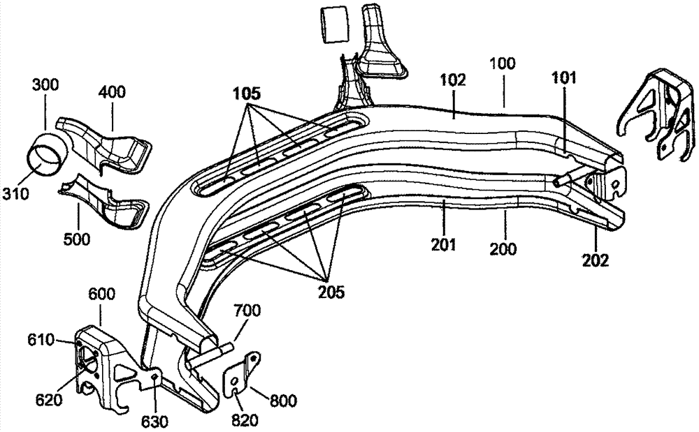
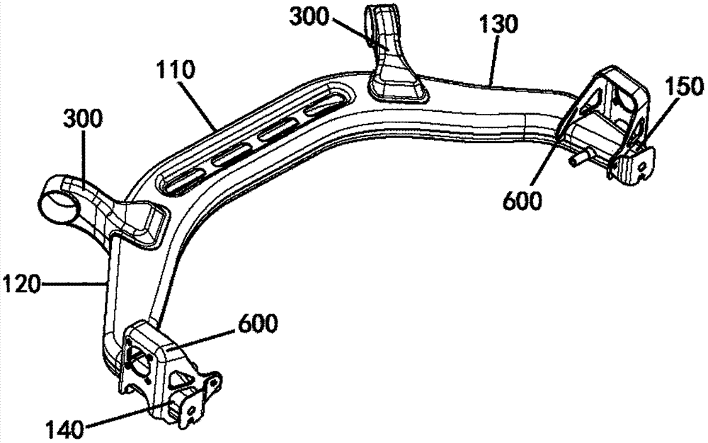
[0023] Such as Figure 2-5 As shown, the torsion beam welding assembly structure of this embodiment includes two facades 101 of a channel-shaped upper plate 100 with a "C"-shaped cross-section and two groove-shaped lower plates 200 with a "C"-shaped cross-section. Facade 201 is a sheet metal structure formed by fastening and welding, such as Figure 4 As shown, the overlap between the upper and lower panels is generally controlled at about 5mm. The sheet metal structure is divided into a beam section 110 located in the middle, a left end section 140 located at the left end, a right end section 150 located at the right end, a left transition section 120 located between the beam section 110 and the left end section 140, and a section located between the beam section 110 and the right end. The right transition section 130 between the parts 150; wherein the left end section 140 and the right end section 150, the left transition section 120 and the right transition section 130 are...


PUM


Abstract

The invention relates to a torsion beam welding assembly structure and belongs to the technical field of automobile design and manufacture. The torsion beam welding assembly structure comprises a sheet metal structure formed by welding in a fastened mode two vertical surfaces of a C-section-shaped grooved upper plate and two vertical surfaces of a C-section-shaped grooved lower plate; the sheet metal structure is composed of a middle beam section, a left end and a right end at both ends of the middle beam section, and left and right transitional sections between the middle beam section and thetwo ends; the left end and the right end, as well as the left transitional section and the right transitional section, are structurally symmetric. The torsion beam welding assembly structure integrates a left longitudinal arm and a right longitudinal arm with the cross beam without T-shaped lap welding, and has a cross section in a closed structure, thereby being higher in fatigue performance than common open beams; meanwhile, the torsion beam welding assembly structure is regular in integral shape, smooth in welding joints, capable of reducing the number of the welding joints, and favorableto achieving robot welding.

Description

technical field [0001] The invention relates to the technical field of automobile design and manufacture, more specifically, the invention relates to a torsion beam welding assembly structure. Background technique [0002] figure 1 It shows the conventional torsion beam welding assembly structure in the prior art, in which the torsion beam beam usually adopts a single-plate open structure (a torsion bar can be welded inside) or a closed-section beam formed by internal high pressure forming, and the end of the beam is connected to the The trailing arm is welded in a T-shape lap joint. This torsion beam welded assembly structure in the prior art has the following technical problems: [0003] 1) The beam and the longitudinal arm are welded, which is prone to stress concentration areas; [0004] 2) The edge of the open beam is prone to stress concentration due to manufacturing defects, reducing fatigue life; [0005] 3) The internal high-pressure formed beam cannot add torsi...

Claims


Application Information

Patent Timeline
IPC IPC(8): B60G21/05B60G21/055
CPCB60G21/05B60G21/055
Inventor 王雷高海龙李力
Owner IAT AUTOMOBILE TECH
Why Eureka
Try Eureka