Work vehicle and work vehicle control method

a technology of work vehicle and control method, which is applied in the direction of analogue processes, instruments, and specific applications for specific applications, can solve the problems of slow actuation of work implements, reduced work efficiency, and ineffective use of lockup travel during work, so as to minimize the effect of improving fuel consumption and reducing the reduction of work efficiency

Active Publication Date: 2015-03-10
KOMATSU LTD
View PDF8 Cites 5 Cited by
  • Summary
  • Abstract
  • Description
  • Claims
  • Application Information

AI Technical Summary

Benefits of technology

[0005]A work vehicle such as that described above is not limited to travel alone; the work implement is sometimes driven while the vehicle is traveling. In such a state, the engine speed is reduced when the lockup clutch is placed in a connected state, whereby the discharge rate of the hydraulic fluid from the hydraulic pump is reduced. In this case, the actuation of the work implement slows and work efficiency is reduced.

Problems solved by technology

In this case, the actuation of the work implement slows and work efficiency is reduced.
Therefore, lockup travel is not actually effectively used during work as described above, regardless of the excellent effect in which fuel consumption is reduced to below that of torque conversion travel.
At this time, a large load is imposed on the work implement.
In particular, a larger load is imposed on the work implement as the operation amount of the work implement operation member increases.

Method used


Image

  • Work vehicle and work vehicle control method
  • Work vehicle and work vehicle control method
  • Work vehicle and work vehicle control method

Examples


Embodiment Construction

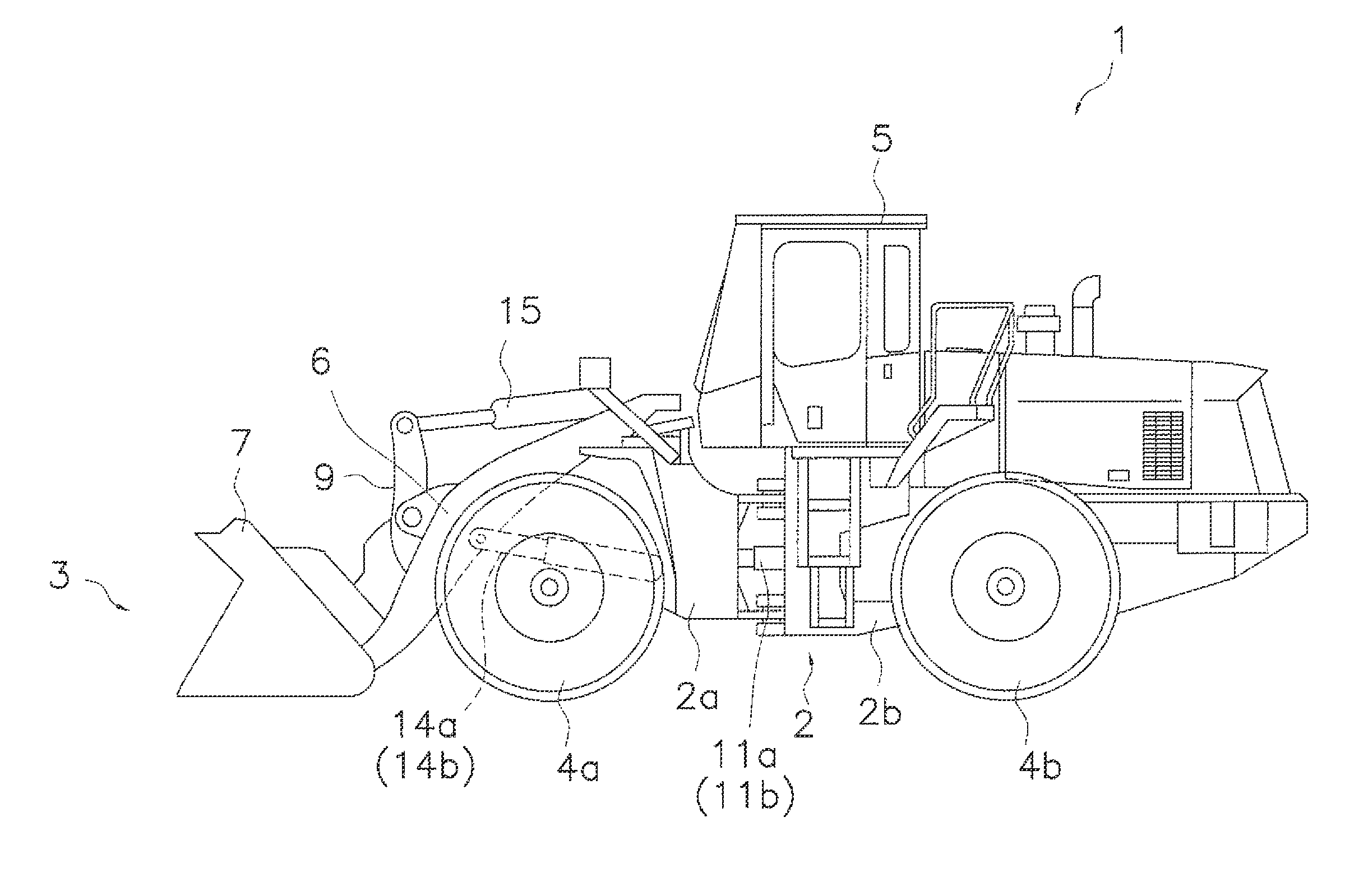
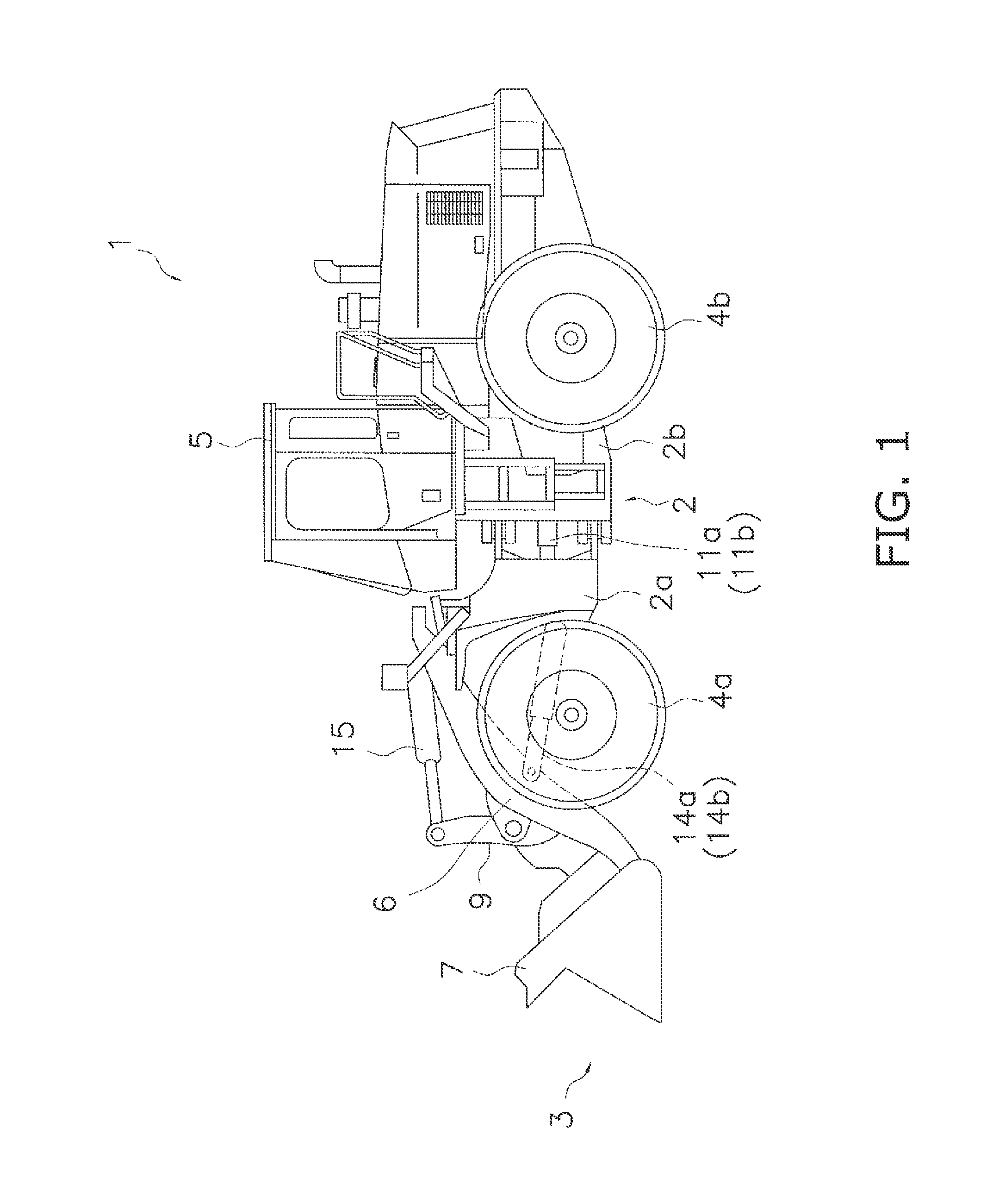
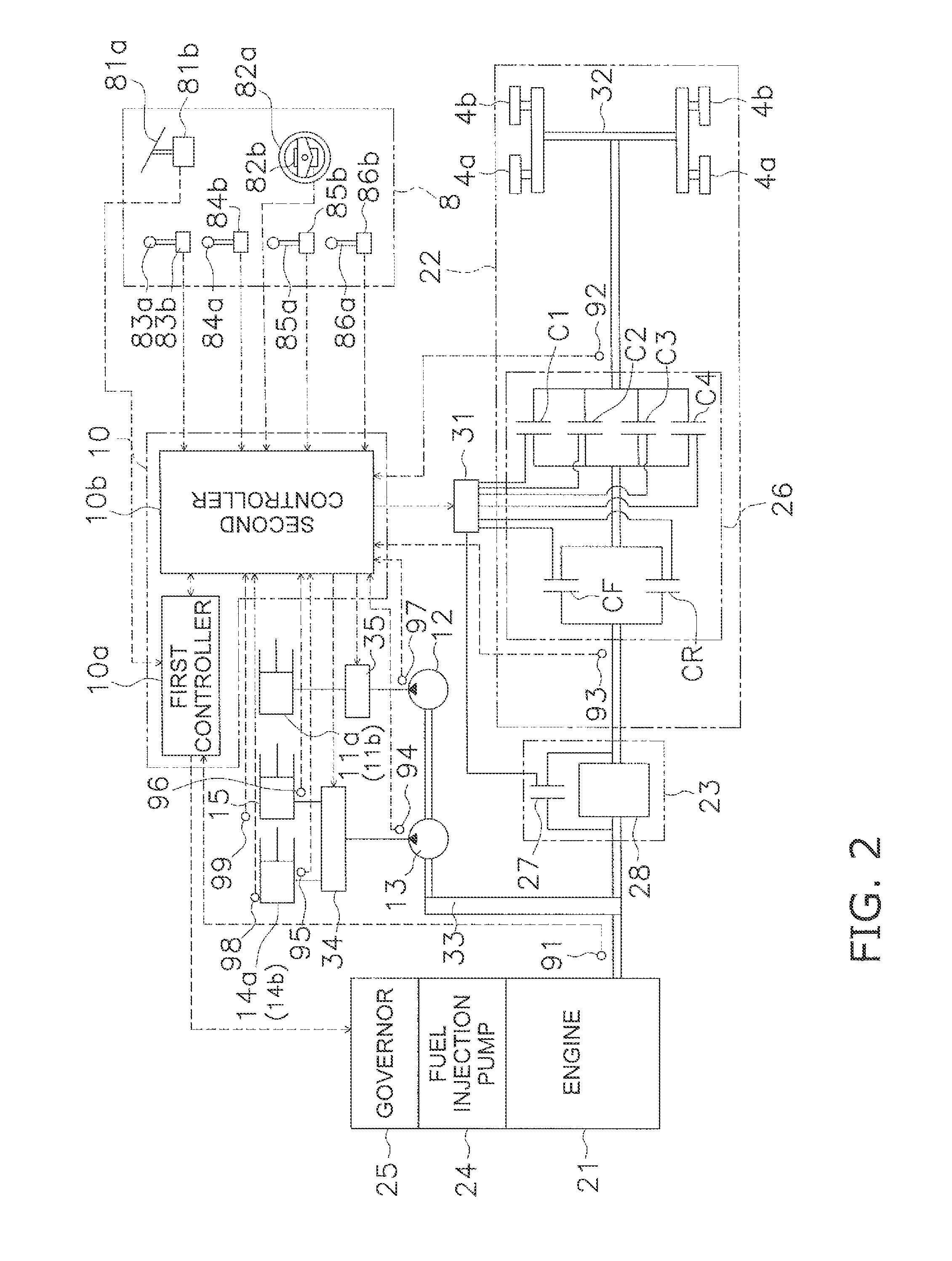
[0038]The work vehicle 1 according to an embodiment of the present invention is shown in FIGS. 1 and 2. FIG 1 is a view of the external appearance of the work vehicle 1, and FIG. 2 is a schematic view showing the configuration of the work vehicle 1. The work vehicle 1 is a wheel loader, and the work vehicle 1 is capable of traveling by front wheels 4a and rear wheels 4b being rotatably driven, and is capable performing desired work using a work implement 3.

[0039]The work vehicle 1 comprises a vehicle body frame 2, a work implement 3, front wheels 4a, rear wheels 4b, and a driver cab 5, as shown in FIG 1.

[0040]The vehicle body frame 2 has a front vehicle body section 2a and a rear vehicle body section 2b. The front vehicle body section 2a and the rear vehicle body section 2b are connected to each other so as to allow pivoting in the left and right directions. A pair of steering cylinders 11b are provided from the front vehicle body section 2a to the rear vehicle body section 2b. The ...


PUM


Abstract

A work vehicle includes an engine, a travel device, a hydraulic pump, a work implement, a torque converter device, and a controller. The torque converter includes a torque converter and a lockup clutch. The controller is configured to switch the lockup clutch between a connected state and a non-connected state in accordance with a travel state of the work vehicle. The controller is configured to determine whether load increase conditions associated with an increase in load on the work implement are satisfied, and to control the lockup clutch so that the lockup clutch is in the non-connected state when the load increase conditions are satisfied.

Description

CROSS-REFERENCE TO RELATED APPLICATIONS[0001]This application claims priority to Japanese Patent Application No. 2010-031463 filed on Feb. 16, 2010, the disclosure of which is hereby incorporated herein by reference in its entirety.TECHNICAL FIELD[0002]The present invention relates to a work vehicle and a work vehicle control method.BACKGROUND ART[0003]In a wheel loader or other work vehicle, a travel device and hydraulic pump are driven by a drive force from an engine. Driving of the travel device causes the vehicle to travel. Driving the hydraulic pump causes hydraulic fluid to be fed from the hydraulic pump to the work implement. The work implement is thereby driven.[0004]There are also work vehicles comprising a torque converter device having a torque converter and a lockup clutch. The torque converter device transmits the drive force from the engine to the travel device via the torque converter when the lockup clutch is in a non-connected state (this state is hereinafter referr...

Claims


Application Information

Patent Timeline
Patent Type & Authority Patents(United States)
IPC IPC(8): E02F9/20F16H61/14
CPCF16H61/143E02F9/202E02F9/2079B60Y2200/41
Inventor FUKUHARA, SATOSHIYAHATA, MAKITONAKANISHI, YUKIHIRO
Owner KOMATSU LTD
Why Eureka
Try Eureka