Two-part channel cross member

a cross member and two-part technology, applied in the direction of walls, constructions, building components, etc., can solve the problems of difficult if not impossible, use of short cross runners or tees with conventional end connections for this purpose, and achieve the effect of simple vertical motion, convenient assembly and less time and skill

Active Publication Date: 2015-03-31
USG INTERIORS INC
View PDF14 Cites 5 Cited by
  • Summary
  • Abstract
  • Description
  • Claims
  • Application Information

AI Technical Summary

Benefits of technology

[0005]The two-part cross member facilitates its assembly into a narrow channel because the visible three-dimensional cover part can be located with simple vertical motion onto the carrier part. Consequently, whereas the carrier part may require manipulation in a plane or planes to insert its ends in a pair of opposed cross runner slots, the three-dimensional cover part need not be subjected to the same. These separate installation steps can be, in total, less demanding in time and skill than what could be required if a single part was used.

Problems solved by technology

Use of short cross runners or tees with conventional end connections for this purpose has proven to be difficult if not impractical.

Method used


Image

  • Two-part channel cross member
  • Two-part channel cross member
  • Two-part channel cross member

Examples


Embodiment Construction

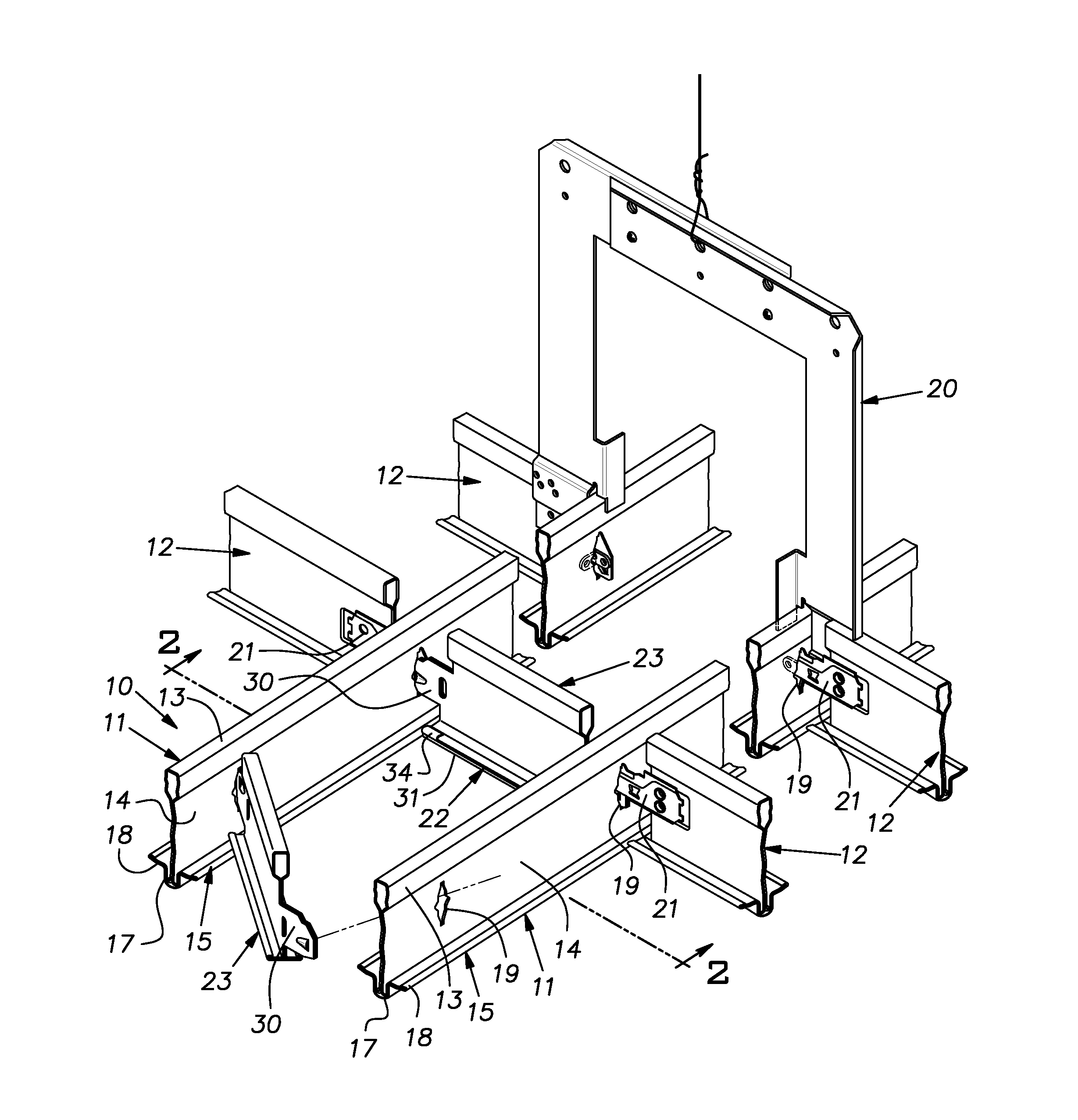
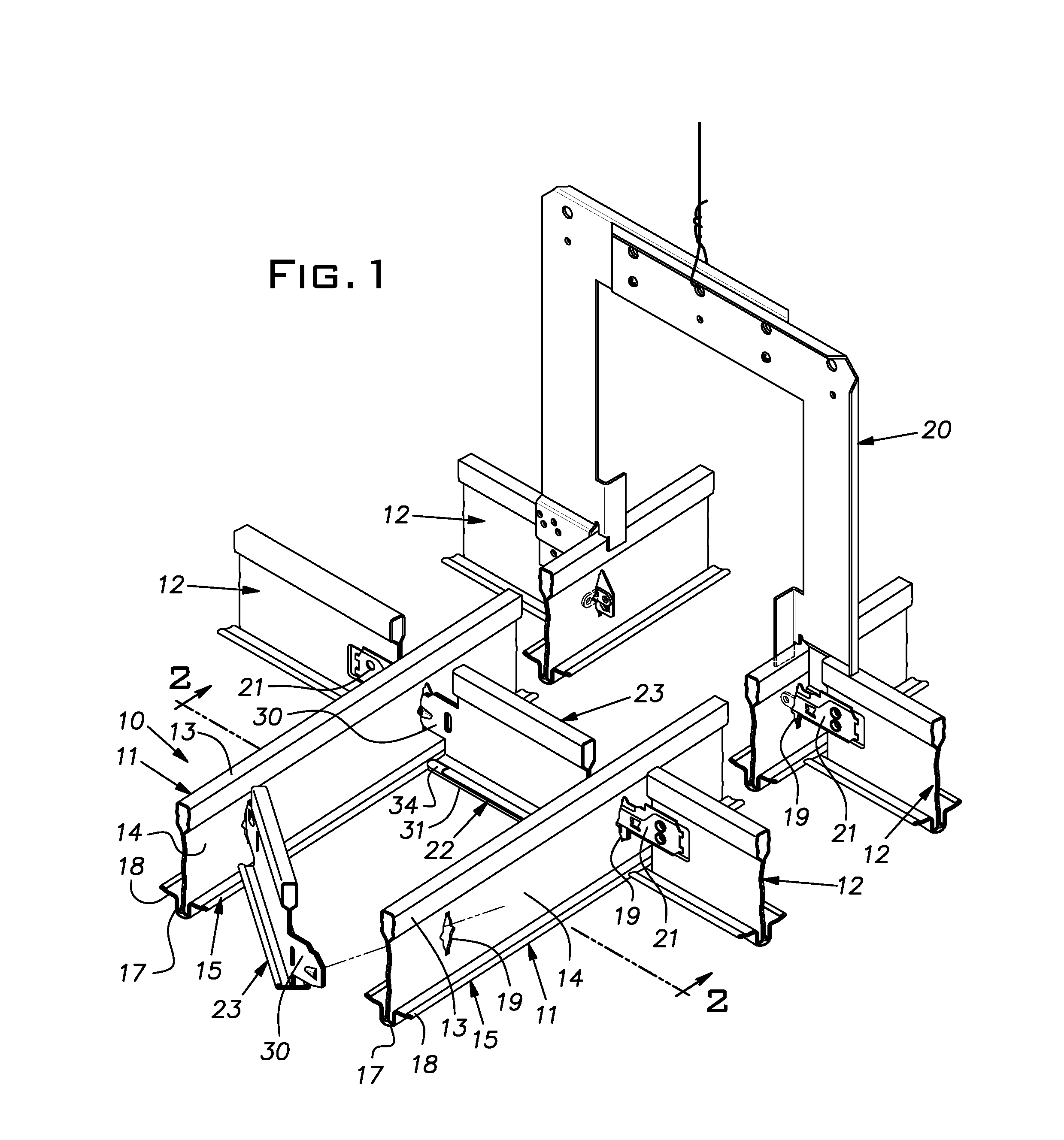
[0011]FIG. 1 illustrates a narrow channel 10 formed of a pair of parallel main runners 11. For visual harmony, the main runners 11 forming the channel 10, as is typical, have the same visible cross-section as that of the grid members of a suspended ceiling in which the channel is integrated. This commonality is represented by cross runners 12 of the suspended ceiling that intersect the channel main runners 11. The illustrated runners 11 and 12 are of the type disclosed in U.S. Pat. No. 8,359,801. The main runners 11 are elongated roll formed sheet metal members having an upper hollow reinforcing bulb 13, a vertical web 14 and a flange 15. The flange 15, unlike a common grid tee flat or planar flange, is three-dimensional, having a U-shaped hollow center 17 and outwardly extending generally horizontal ribs 18.

[0012]The main runner webs 14, as is normal, have regularly spaced vertical slots 19 for receiving end connectors 21 of intersecting cross runners 12. The opposed slots 19 of th...


PUM


Abstract

A cross member for a narrow channel in a suspended ceiling grid comprising a carrier and a cover, the carrier having a web and a planar flange on a lower edge of the web, end connectors at opposite ends of the carrier web, the cover having a three-dimensional cross-section with an overall width generally equal to the width of the carrier flange and integral bendable tabs, the tabs being adjacent the ends of the cover and short in comparison to a length of the cover, the tabs being constructed to be manually folded over the flange of the carrier to lock the cover to the carrier.

Description

BACKGROUND OF THE INVENTION[0001]The invention relates to suspended ceiling construction and, in particular, to grid elements used with narrow utility channel systems.PRIOR ART[0002]Narrow channel systems are available for housing or otherwise locating various utility hardware in a conventional rectangular ceiling grid and tile construction. The channels are viewed as more harmonious or attractive than conventional arrangements for locating lights, air diffusers and returns, sprinklers and the like. Conventional arrangements, for example, dedicate a full grid module space to a single utility and, consequently, are more visually prominent than what is ordinarily needed to house a particular utility. The subject narrow channel systems, besides reducing the visibility of necessary utilities, can add to the attractiveness of a ceiling.[0003]It is known to construct narrow utility channels by aligning a pair of conventional main runners or tees in close parallel relation. A number of inv...

Claims


Application Information

Patent Timeline
Patent Type & Authority Patents(United States)
IPC IPC(8): E04C2/52E04B9/12
CPCE04B9/122E04B9/068E04B9/18E04B2009/062
Inventor LEHANE, JR., JAMES J.GULBRANDSEN, PEDER J.PAULSEN, MARK R.UNDERKOFLER, ABRAHAM M.
Owner USG INTERIORS INC
Why Eureka
Try Eureka