
Measuring a temperature during contactless transmission of energy

Active Publication Date: 2015-03-31
AUDI AG
View PDF17 Cites 1 Cited by
  • Summary
  • Abstract
  • Description
  • Claims
  • Application Information

AI Technical Summary

Benefits of technology

The invention aims to make it safer to charge a motor vehicle's battery without physical contact.

Problems solved by technology

Under certain circumstance, these articles may heat up to such an extent as to cause fire or burns.

Method used


Image

  • Measuring a temperature during contactless transmission of energy
  • Measuring a temperature during contactless transmission of energy

Examples


Embodiment Construction

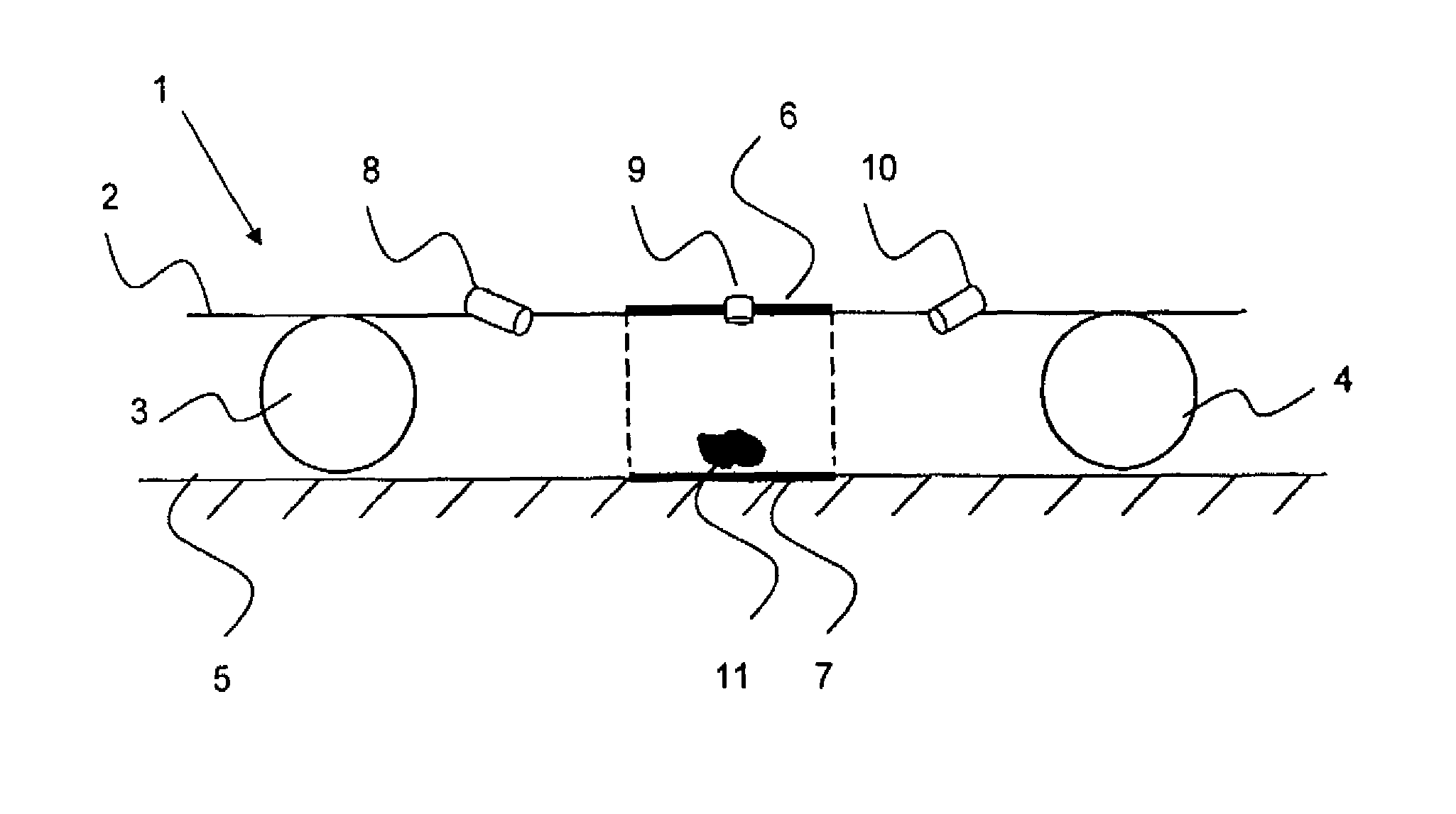
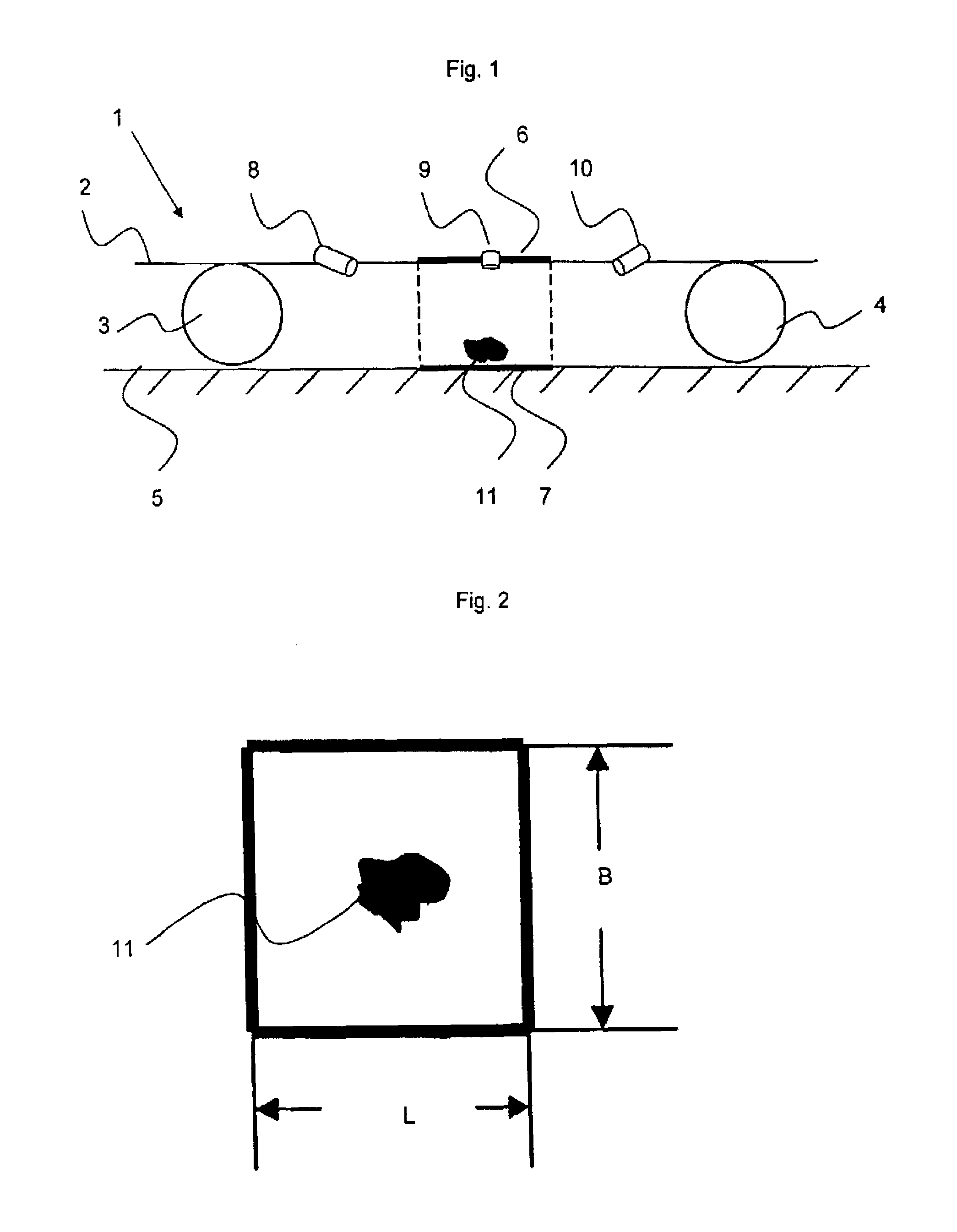
[0021]FIG. 1 shows a motor vehicle 1 with a subfloor 2 and wheels 3, 4 standing on a roadway 5.

[0022]One or more of the wheels 3, 4 are propelled by an electric motor which receives energy from a traction battery. This battery can be charged by an apparatus for the contactless transmission of energy, including a receiver 6 for receiving the energy for charging. The receiver 6 is configured as a coil in the subfloor 2 of the motor vehicle 1.

[0023]The receiver 6 of the apparatus for the contactless transmission of energy receives the energy for charging the battery from a transmitter 7 which is arranged on the roadway 5.

[0024]The apparatus for the contactless transmission of energy includes a measuring device for measuring a temperature between the transmitter and the receiver, including a sensor system having three sensors 8, 9, 10 and arranged on the subfloor (underbody) 2 of the motor vehicle 1. According to an especially cost-efficient variation, the sensor system may include only...


PUM


Abstract

During contactless transmission of energy between a receiver (6) for receiving the energy and a transmitter (7) for transmitting the energy for the purpose of charging a battery of a motor vehicle (1), a temperature is measured in a region between the transmitter (7) and the receiver (6).

Description

CROSS-REFERENCES TO RELATED APPLICATIONS[0001]This application is the U.S. National Stage of International Application No. PCT / EP2011 / 003315, filed Jul. 5, 2011, which designated the United States and has been published as International Publication No. WO 2012 / 003957 and which claims the priority of German Patent Application, Serial No. 10 2010 026 780.5, filed Jul. 9, 2010, pursuant to 35 U.S.C. 119(a)-(d).BACKGROUND OF THE INVENTION[0002]The invention relates to the contactless transmission of energy for charging a battery of a motor vehicle.[0003]A charging process of traction batteries in electric or hybrid vehicles is normally executed in the absence of a person during the entire changing process. Therefore, this process has to be designated primarily as an unsupervised charging.[0004]Contactless transmission of energy generates a high magnetic flux density which is especially great in the region between the transmitter of energy and the receiver of the energy. This magnetic fi...

Claims


Application Information

Patent Timeline
IPC IPC(8): G01K1/00B60L3/00B60L11/18G01K13/00H01M10/44H02J7/02H02J7/04
CPCG01K13/00B60L3/0092B60L11/182H01M10/443H02J7/025H02J7/027H02J7/047B60L2240/36Y02T10/7005Y02T10/7088Y02T90/122Y02T90/14Y02T10/7072B60L2240/662Y02T90/16B60L53/124B60L53/126H02J50/10H02J50/60H02J7/007192Y02T10/72Y02T10/70Y02E60/10H02J7/02H02J7/0047Y02T90/12
Inventor ELIAS, BJORNSCHMIDT, FLORIAN
Owner AUDI AG
Learn More