
Device for machining edges

Active Publication Date: 2016-06-16
AIRBUS DEFENCE & SPACE
View PDF27 Cites 2 Cited by
  • Summary
  • Abstract
  • Description
  • Claims
  • Application Information

AI Technical Summary

Benefits of technology

The invention is a machining tool that can rotate around a central guide pin and be guided on the workpiece by its tip. It can also be guided on the workpiece by a table that is adjustable in both movement and angle. This allows the tool to reach the workpiece from all sides while keeping its overall height low. The invention is suitable for machining complex geometries, such as visible and non-visible edges, and can also be used for hand-held machining of workpieces on stationary objects or difficult-to-access operating sites. The invention provides an interchangeable tip for the guide pin, which makes it easy to adjust the cutting depth and reduces friction between the guide pin and the workpiece. This enhances the device's flexibility for different machining cases.

Problems solved by technology

For edges that are present on the workpiece, for example for recesses or grooves, the overarching guiding element however usually presents a limitation to the machining options owing to the size of said element and the connection to the machining table, which lies outside the tool.
Particularly narrow grooves, shallow recesses, edges having short radii and acute angles, thus particularly complex geometries, often cannot be produced thereby, or can only be produced with difficulty.
This may be due to the fact that the L-shaped guiding element is too high for shallow recesses and too wide for narrow grooves.
In addition, machining whilst simultaneously monitoring the work result in internal machining operations that are covered by the workpiece is only possible with difficulty.
This potentially incorrect assumption and the resulting unsatisfactory machining of a workpiece is usually only eliminated by a subsequent check and by lifting up the workpiece, as is associated with said check, and this may possibly require extra work if the quality is inadequate.
The resulting cut edges, in particular in aluminium, are deburred and smoothed using simple scraping or geometrically undefined abrasive tools, owing to the shape of the repair site and the fact that it is often difficult to access.
In both cases, defined geometric machining of the edges is usually not possible.
The high-strength fibres may, for example, be torn from the matrix during machining, these defects representing the start of cracks.

Method used


Image

  • Device for machining edges
  • Device for machining edges
  • Device for machining edges

Examples


Embodiment Construction

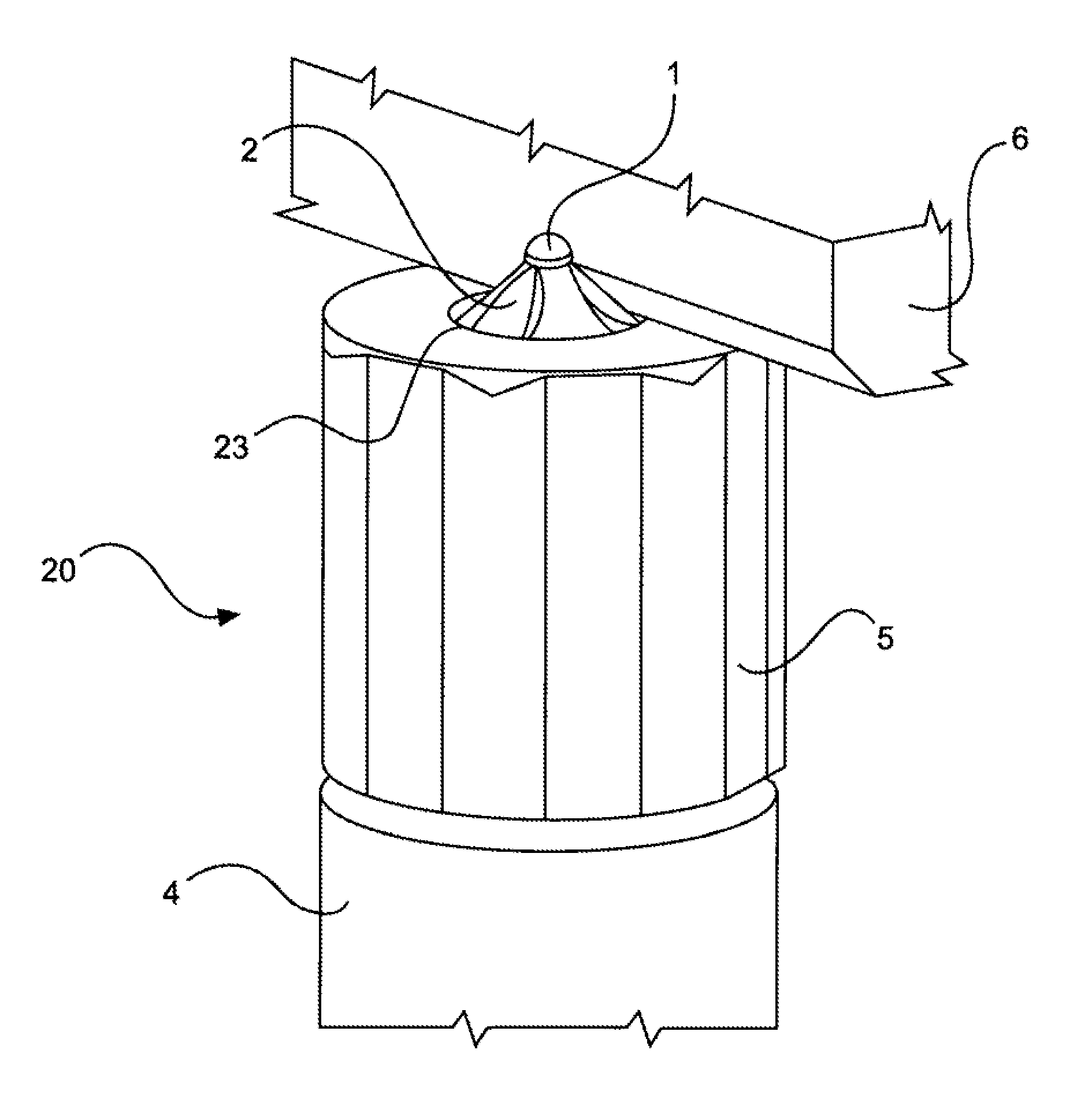
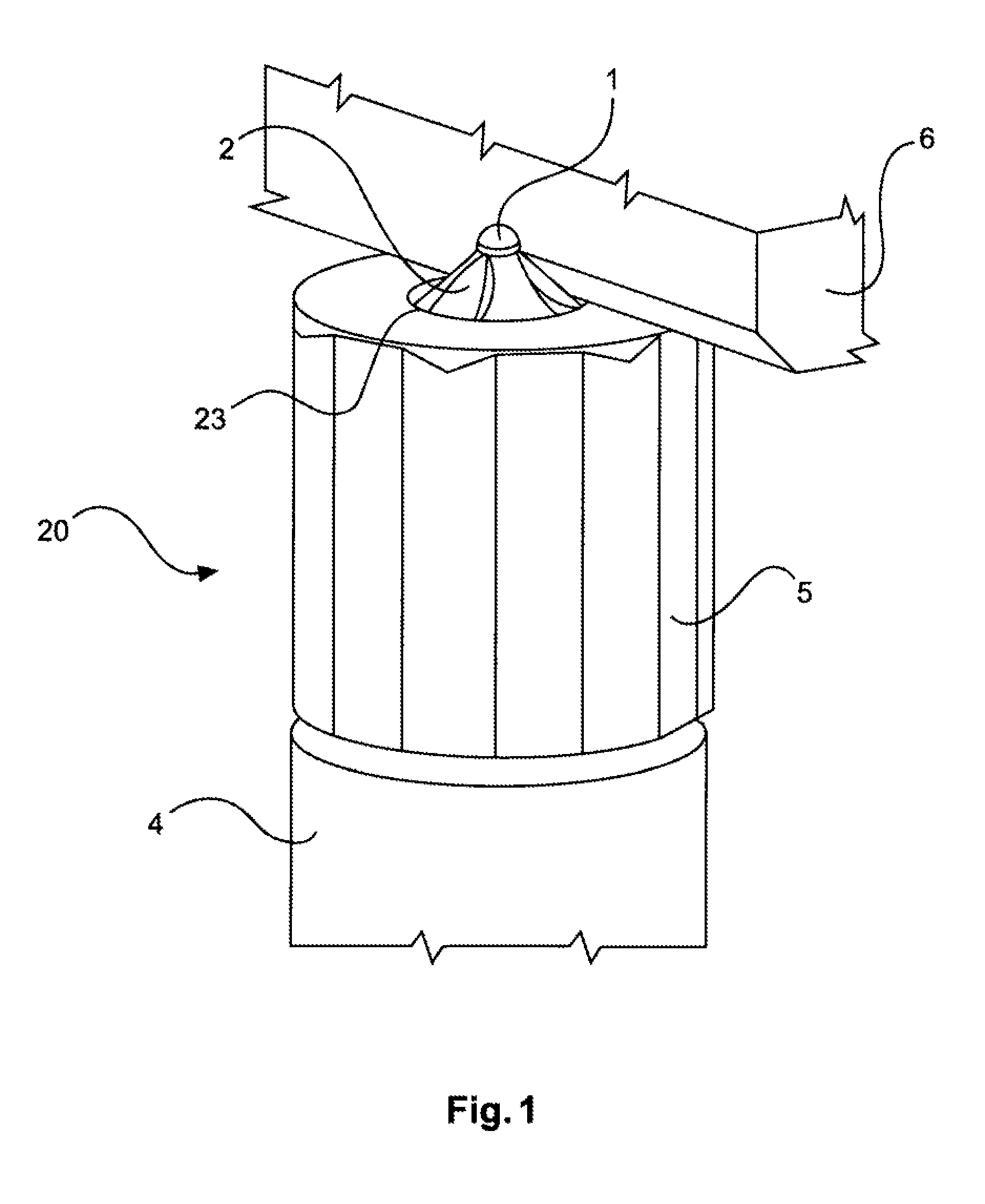
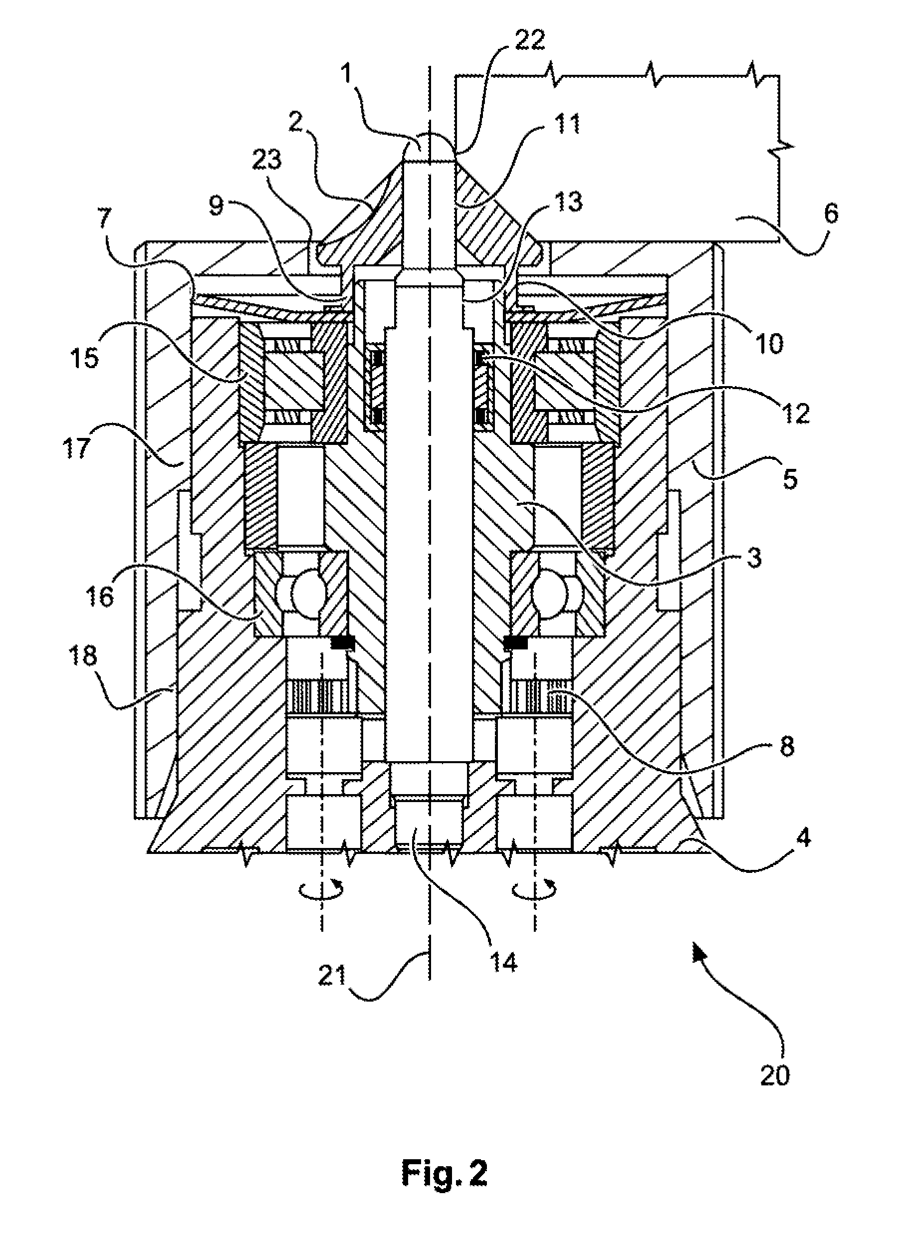
[0027]The device according to an embodiment of the invention from FIGS. 1 and 2 comprises a first workpiece-guiding element 1, and a central and substantially rotationally symmetrical guide pin 1 which extends through and projects beyond a machining tool 2 in a coaxial hole 22. Towards its base, the diameter of the first workpiece-guiding element 1 increases continuously or in a stepped manner, or its diameter varies. Between the rounded tip (the upper, outwardly projecting end) of the first workpiece-guiding element 1 and its base (the lower, inner end), there is a key face 13 and a running surface / support surface for a bearing point, for example a needle bearing 12. At its base, the first workpiece-guiding element 1 comprises an element for detachable connection, for example a thread 14 and, if necessary, a centring means in order for it to be possible to connect the first workpiece-guiding element 1 to a main body 4 and if necessary to centre it with respect thereto.

[0028]The mac...


PUM

PropertyMeasurementUnit
Diameteraaaaaaaaaa

Abstract

A device for machining workpieces a machining tool, a first workpiece-guiding element and a second workpiece-guiding element. The first workpiece-guiding element and the second workpiece-guiding element are designed to guide a workpiece, in a defined way, relative to the machining tool. The machining tool has an axis of rotation and a co-axial opening. The machining tool rotates about the axis of rotation for machining the workpiece. The first workpiece-guiding element is arranged in the opening of the machining tool co-axially to the axis of rotation.

Description

CROSS-REFERENCE TO RELATED APPLICATIONS[0001]The present application is a national phase entry under 35 U.S.C. §371 of International Application No. PCT / DE2014 / 000362 filed on Jul. 17, 2014, published in German, which claims priority from German Patent Application No. 10 2013 012 167.1 filed on Jul. 20, 2013, all of which are incorporated herein by reference.FIELD OF THE INVENTION[0002]The present invention relates to tool technology. In particular, the present invention relates to a device for machining workpieces, with a particular focus on chamfering, smoothing, contour milling and deburring workpiece edges. Here, the workpiece may be guided on the device or the device may be guided on the workpiece manually by the operator along the workpiece contour, and the material to be removed may be machined using a separately driven and rotating machining tool.BACKGROUND OF THE INVENTION[0003]The machining of semi-finished workpiece edges in individual manufacturing steps is used in large...

Claims


Application Information

Patent Timeline
IPC IPC(8): B23C3/12
CPCB23C3/126B23C2220/16B23C2255/12B23C2230/04B23C2220/20B23C3/12Y10T409/304144
Inventor DAUNER, TIMO
Owner AIRBUS DEFENCE & SPACE
Learn More