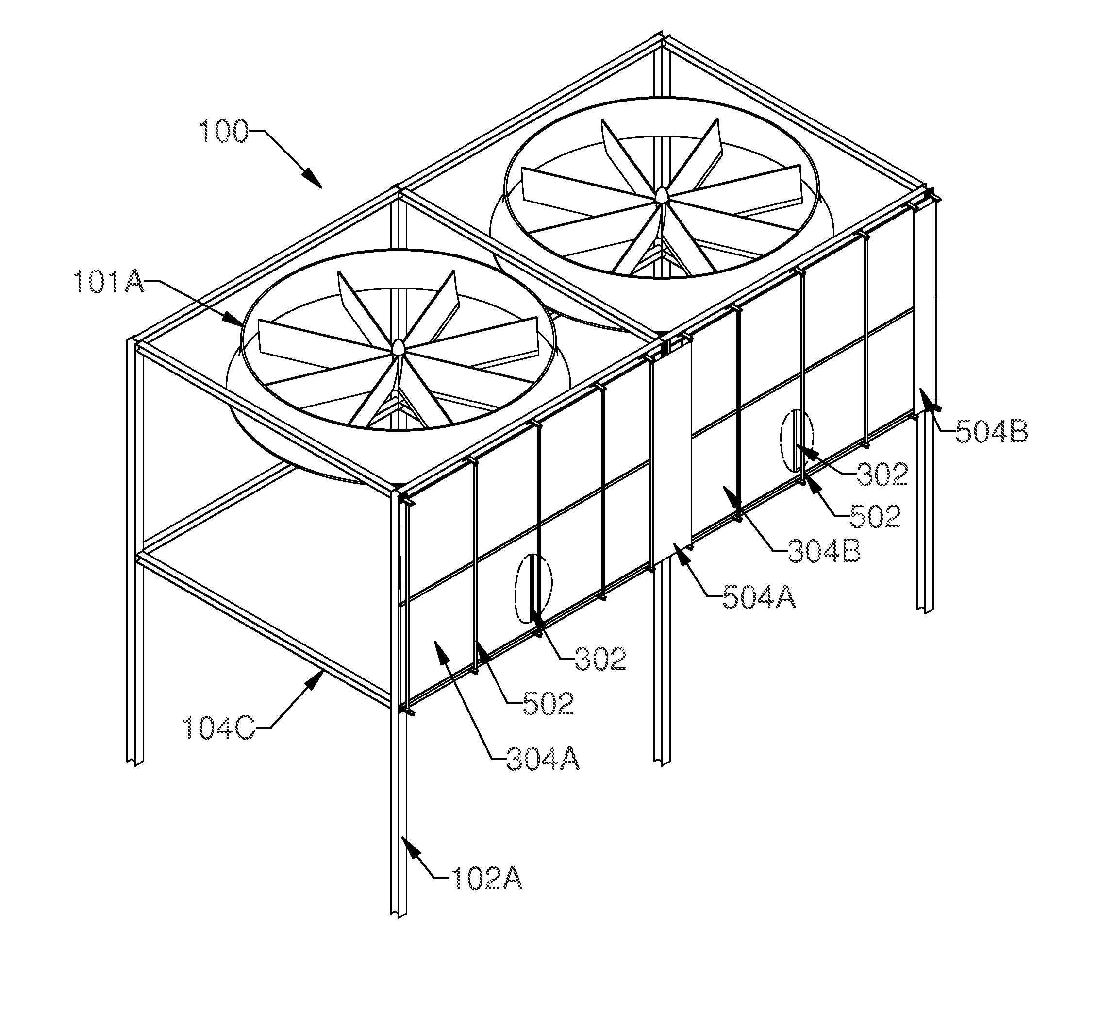
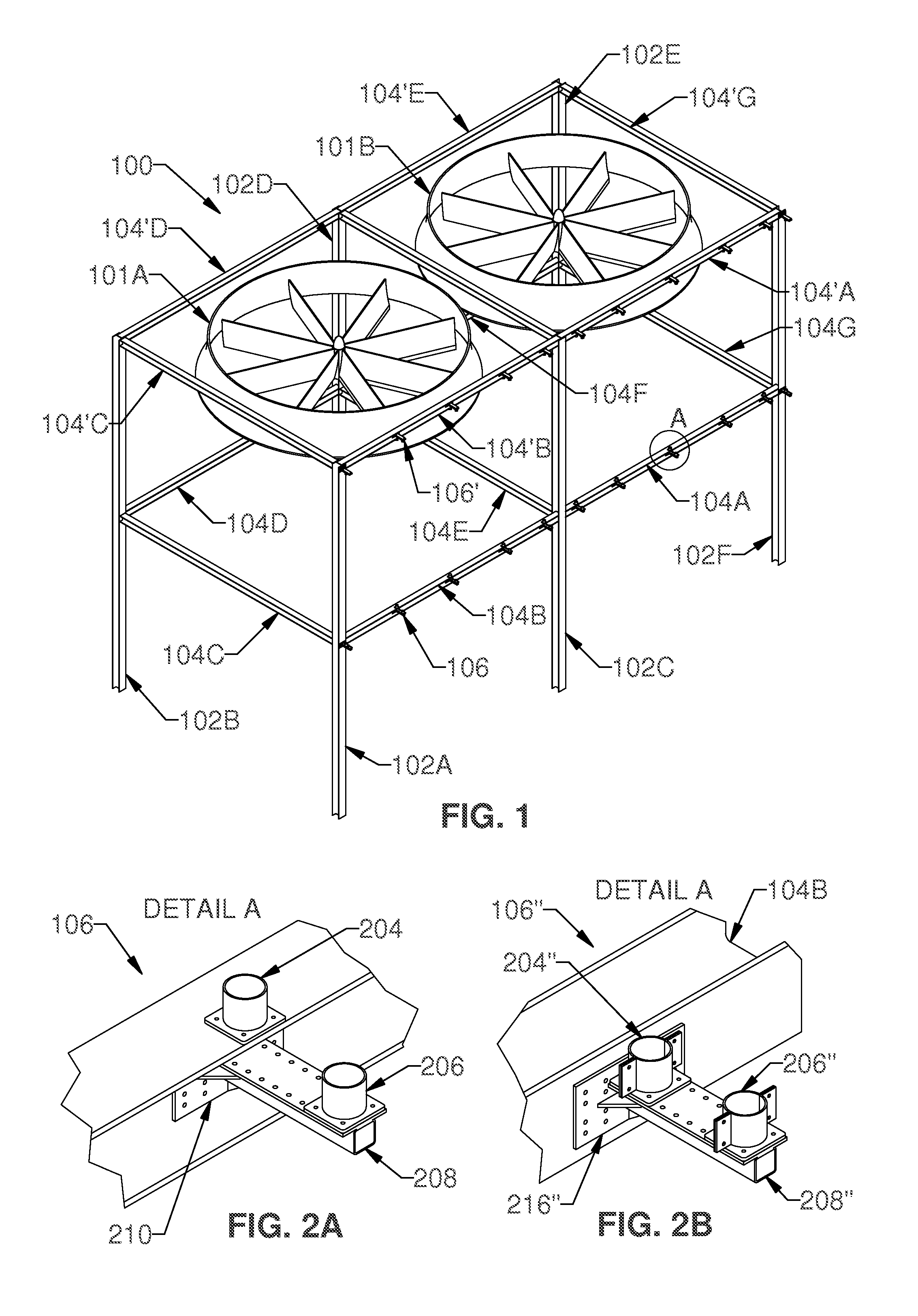
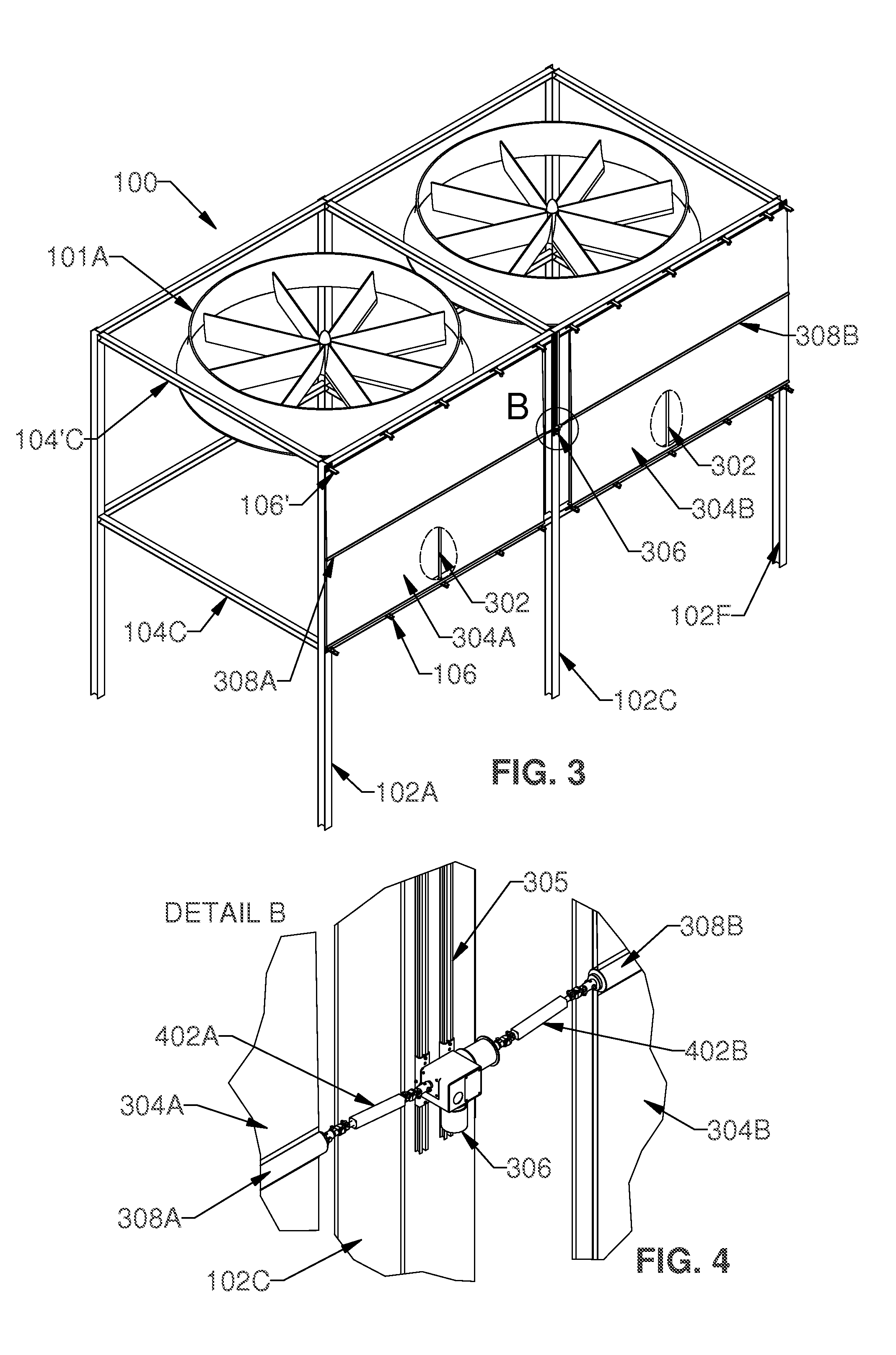
Shield system
a shielding system and shielding technology, applied in the direction of curtain suspension devices, heating types, building components, etc., can solve the problems of affecting the efficiency of air coolers, stalling of the air column in the fans, and low fan performan
- Summary
- Abstract
- Description
- Claims
- Application Information
AI Technical Summary
Benefits of technology
Problems solved by technology
Method used
Image
Examples
second embodiment
[0061]Turning to FIG. 7, an example of another shield system that may be installed instead of, or in addition to, the example described above is shown. the shield comprises a fixing arrangement that includes a first curved member 702A that is connected to a lower surface of horizontal side upper strut 104′C and an inner surface of end upright 102A. One end of the member 702 is located about one sixth to one quarter of the distance between 104C and 104′C above the point where lower horizontal struts 104 connect to the upright 102A. Its other end is located about one sixth to one quarter of the distance between 102A and 102B from the point where the upper horizontal struts 104′ meet upright 102B. There is a corresponding second curved member 702B having one end fixed to a corresponding location on the inner surface of middle upright 102C and its other end fixed to the lower surface of middle upper horizontal strut 104′E. There is also a third curved member 702B extending in a similar ...
first embodiment
[0064]FIG. 8 shows the shield system with a first lower sheet 802A fitted between curved members 702A and 702B. There is also a second lower sheet 802B fitted between curved members 702B and 702C. The system further includes a first upper sheet 804A fitted between curved members 704A and 704B, as well as a second upper sheet 804B between curved members 704B and 704C. The sheets may be fitted between the curved members by means of tensioning arrangements comprising straps 811 and clamps 813 as shown in FIG. 8A (and similar to the shields described in WO 2005 / 018745 in the name of GBR Industries Limited). Alternatively, as with the first embodiment described above, the system may include a motor for adjusting the position of the sheets, although this can also be done manually. In use, energy from wind blowing in the direction of the arrows can be diverted upwards to boost the performance of the fans of the AC. Thus, the system allows external wind power to be harnessed and used to ben...
third embodiment
[0065]FIG. 8B shows a further example of a shield system that may be installed instead of, or in addition to, the first example described above. the shield comprises a fixing arrangement that includes an upper angled elongate member 882A that is connected to an inner side surface of end upright 102A (adjacent its upper end) and a lower angled elongate member 884A (nearer where the upright is connected to the horizontal struts). One end of each of the angled members 882A, 884A protrudes into the inner space of the framework 100, whilst its other end depends at an angle outwardly.
[0066]There are corresponding upper and lower angled members 882B, 884B connected to the opposed side surface of central upright 102C. There are further upper and lower angled members 882C, 884C connected in a corresponding manner to the other side surface of central upright 102C, as well as further upper and lower members 882D. 884D connected to the opposed side surface of the other end upright 102F. The ang...
PUM
 Abstract
Description
Claims
Application Information
 - R&D
- Intellectual Property
- Life Sciences
- Materials
- Tech Scout
- Unparalleled Data Quality
- Higher Quality Content
- 60% Fewer Hallucinations
Browse by: Latest US Patents, China's latest patents, Technical Efficacy Thesaurus, Application Domain, Technology Topic, Popular Technical Reports.
© 2025 PatSnap. All rights reserved.Legal|Privacy policy|Modern Slavery Act Transparency Statement|Sitemap|About US| Contact US: help@patsnap.com


