Print carriage

a carriage and printing technology, applied in the field of printing carriages, can solve the problems of not being able to locate two heads next to each other without leaving, and the arrangement is not directly suitable for diagonal operation, so as to reduce the calibration required

Inactive Publication Date: 2015-04-14
XENNIA HOLLAND
View PDF40 Cites 1 Cited by
  • Summary
  • Abstract
  • Description
  • Claims
  • Application Information

AI Technical Summary

Benefits of technology

[0018]The present invention seeks to address at least some of these difficulties by using a single print carriage to deposit both complementary swathes. Accordingly the print carriage comprises a first plurality of inkjet heads arranged to deposit a substance onto the substrate in forward and reverse passes of a first swathe; a second plurality of inkjet heads arranged to deposit the substance onto the substrate in forward and reverse passes of a second swathe, complementary to the first swathe; wherein the first and second plurality of heads are arranged to ensure that the first and second swathes complement one another on both forward and reverse passes. In this context, complementary may be understood to mean that uniform coverage is achieved by superposition of two swathes such that each portion of the substrate is covered either twice by one of the swathes or once by each swathe. It will be understood that any errors occurring due to failure of an individual nozzle will be significantly less visible as a result both of diagonal motion and due to the fact that each portion of the substrate will be addressed twice by different nozzles. By providing the first and second swathes from a single carriage, the offset between the heads that deposit the first and second swathes may be precisely determined and maintained. An alignment means or arrangement may be provided to ensure alignment within the carriage. No alignment and synchronisation between a pair of carriages is thus required, reducing significantly the calibration required at set-up and on changing of print parameters.

Problems solved by technology

It is however not generally possible to locate two heads next to one another without leaving a gap between.
Such an arrangement is not however directly suitable for operation in a diagonal manner in two passes, since the staggered heads cannot align on both diagonal passes.

Method used


Image

  • Print carriage
  • Print carriage
  • Print carriage

Examples


first embodiment

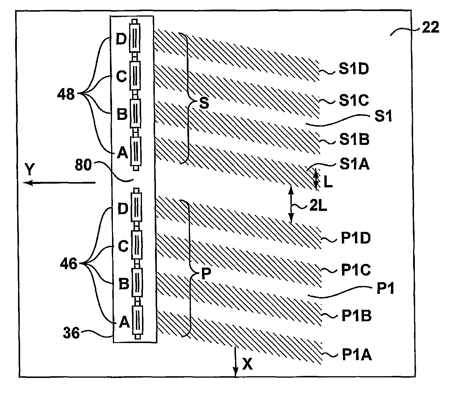
[0072]According to FIG. 6, a single carriage print arrangement according to the invention is depicted in which, for the sake of clarity, only the positions of the heads and nozzles are shown. Like reference numerals denote corresponding elements to those of FIGS. 1 to 5.

[0073]The print carriage 36 comprises a first set 46 of print heads 46 A-D and a second set 48 of print heads 48 A-D. The print heads in each set 46, 48 are Xaar Omnidot™ 760 as those of FIGS. 1 to 5 and each has a head length l. This length l is the effective width over which the head can deposit the substance to be printed and need not correspond to the physical length of the head itself. The print heads are also mutually spaced from adjacent heads within the set by the same distance l. Such a distribution of print heads is hereafter referred to as a comb formation, since operation of the carriage may deposit a substance onto the surface of substrate 22 in swathes P, S as if a comb had been drawn over the surface. ...

second embodiment

[0077]carriage 36 is shown in FIG. 7 in which heads 46 A-D are stacked in two rows, offset from one another in the traverse direction. The heads 48 A-D of the second set 48 are also stacked in a similar manner. As was the case in the embodiment of FIG. 6, the heads 46 A, B are spaced by a distance l, as are the heads 48 A, B, 46 C, D and 48 C, D. Furthermore, according to the invention an alignment means 80 in the form of a double spacing 21 is provided between the first set 46 and the second set 48.

[0078]In use all of the heads of the carriage 36 are used to deposit the same substance onto the substrate 22 in primary and secondary swathes P, S. In this case, the heads are driven to deposit at a resolution of 90 dpi in the traverse direction. Stacking of the heads causes areas of the first pass P1 to be printed twice by both heads 46A and 46C, achieving a resultant definition for the first pass P1 of 180 dpi. Other areas are twice printed by heads 46B and 46 D. Since the carriage 36...

third embodiment

[0082]FIG. 8 shows part of a carriage 36 according to the invention having an alternative arrangement of heads in two sets 46, 48. The heads 46A, B . . . in the first set (only the first two heads are shown) are arranged in comb formation with a head spacing 1. The heads 48 A, B, . . . are also arranged in a similar formation and are offset laterally from the first set 46 by a distance m which serves as an alignment arrangement 80. As can be seen from FIG. 8, at an angle β, the swathe P1B deposited by head 46B passes perfectly between the heads 48 A, B and can complement the swathes S1A, S1B deposited by these heads. For this to occur, the swathe angle α must be set equal to angle β=arctan l / m. The skilled person will understand that since the spacings are equal for each set 46, 48, the heads will also complement each other on the reverse pass when driven at the same angle. The embodiment is however limited to only this swathe angle.


PUM


Abstract

A system and method for depositing a substance onto a continuously moving substrate in first and second transverse swathes, is achieved by providing a print carriage having a first set of inkjet heads and a second set of inkjet heads. The carriage is traversed across the substrate in a forward pass, while depositing the first and second swathes from the respective first and second plurality of inkjet heads and subsequently traversed across the substrate in a reverse pass. The first and second sets of inkjet heads are arranged such that the first and second swathes complement one another on both forward and reverse passes to provide substantially complete coverage of the substrate. In this manner complementary swathes may be deposited from a single head.

Description

CROSS-REFERENCE TO RELATED APPLICATIONS[0001]This application is a continuation of PCT patent application number PCT / EP2010 / 055769 filed on 28 Apr. 2010, which claims priority from United Kingdom patent application number GB 0907362.8 filed on 29 Apr. 2009. Both applications are hereby incorporated by reference in their entireties.BACKGROUND OF THE INVENTION[0002]1. Field of the Invention[0003]The invention relates generally to a print carriage for the deposition of a substance onto a substrate using printing techniques and the like. The invention further relates to a printer provided with such a print carriage and to procedures for performing deposition in a continuous process, in particular in the fields of textile printing and finishing.[0004]2. Description of the Related Art[0005]Systems for inkjet printing of images and text onto a substrate are generally known. Many such systems are adapted to desktop or office application and are well suited for performing printing onto A3 or...

Claims


Application Information

Patent Timeline
Patent Type & Authority Patents(United States)
IPC IPC(8): B41J2/165B41J2/21B41J19/16
CPCB41J2/2132B41J2/21B41J19/16B41J2/2135
Inventor HUDD, ALANKOELE, GERRITBENNET, SIMON
Owner XENNIA HOLLAND
Why Eureka
Try Eureka