Interlocking lighting fixture

a technology of lighting fixtures and interlocking parts, which is applied in the field of lighting fixtures, can solve the problems of limited configurations in which such lighting fixtures may be arranged, and achieve the effect of convenient reconfiguration

Inactive Publication Date: 2015-04-14
0ENERGY LIGHTING
View PDF12 Cites 6 Cited by
  • Summary
  • Abstract
  • Description
  • Claims
  • Application Information

AI Technical Summary

Benefits of technology

[0009]It is a further object of the present invention to provide a lighting fixture which has a polygonally-shaped housing, each side wall of the housing having the capability of interlocking with a side wall of a similarly polygonally-shaped lighting fixture to form a modular arrangement of lighting fixtures, where each fixture of the modular arrangement may be replaced, combined or interchanged easily with another lighting fixture.
[0010]It is yet a further object of the present invention to provide a modular arrangement of interlocking lighting fixtures in which the modular arrangement may be easily reconfigured as desired.
[0011]It is still a further object of the present invention to provide a lighting fixture having interlocking features which overcome the inherent disadvantages of conventional, non-interlocking lighting fixtures.

Problems solved by technology

Even if such conventional individual lighting fixtures are mounted on a common support, such as an elongated bar, the configurations in which such lighting fixtures may be arranged are limited.

Method used


Image

  • Interlocking lighting fixture
  • Interlocking lighting fixture
  • Interlocking lighting fixture

Examples


Embodiment Construction

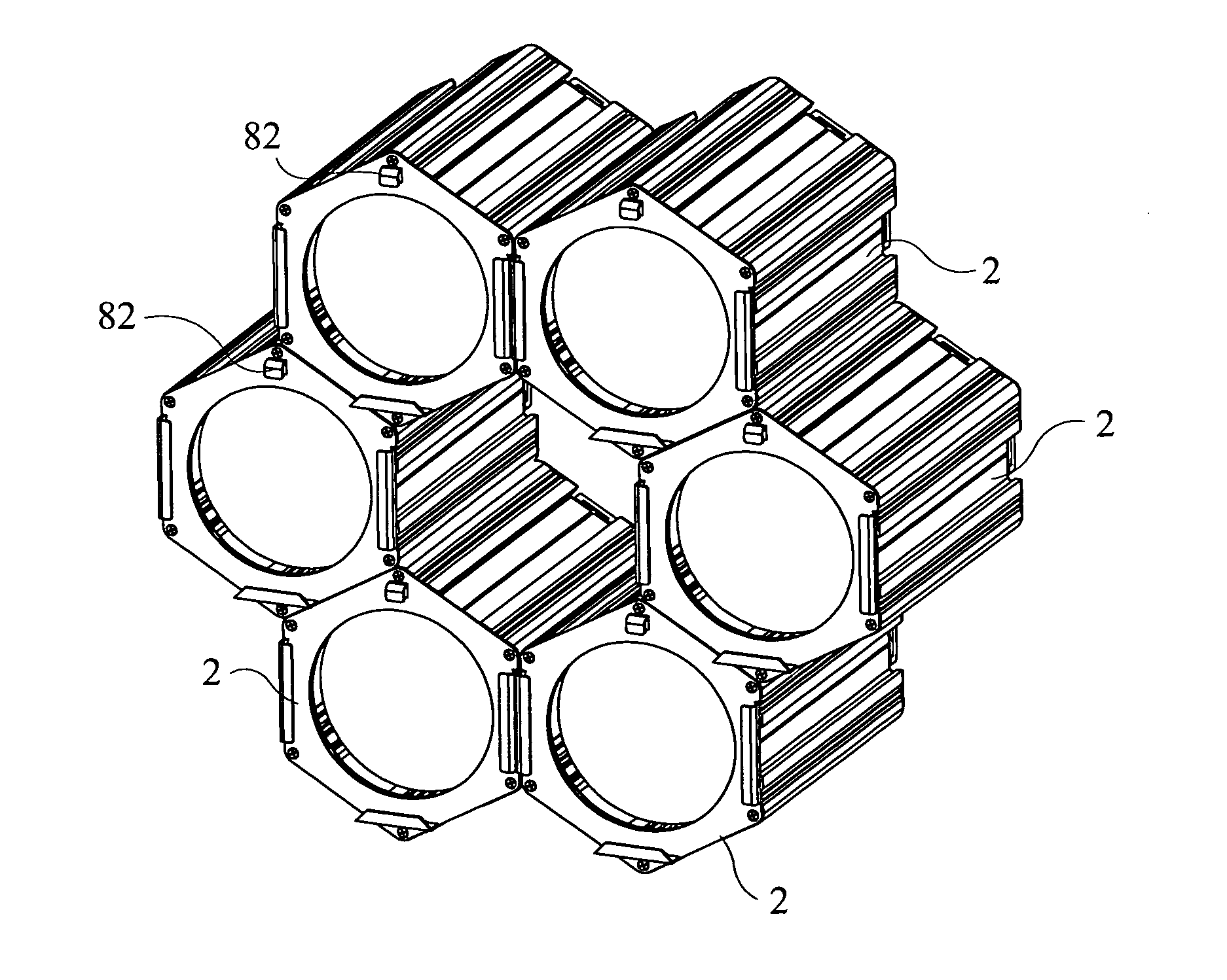
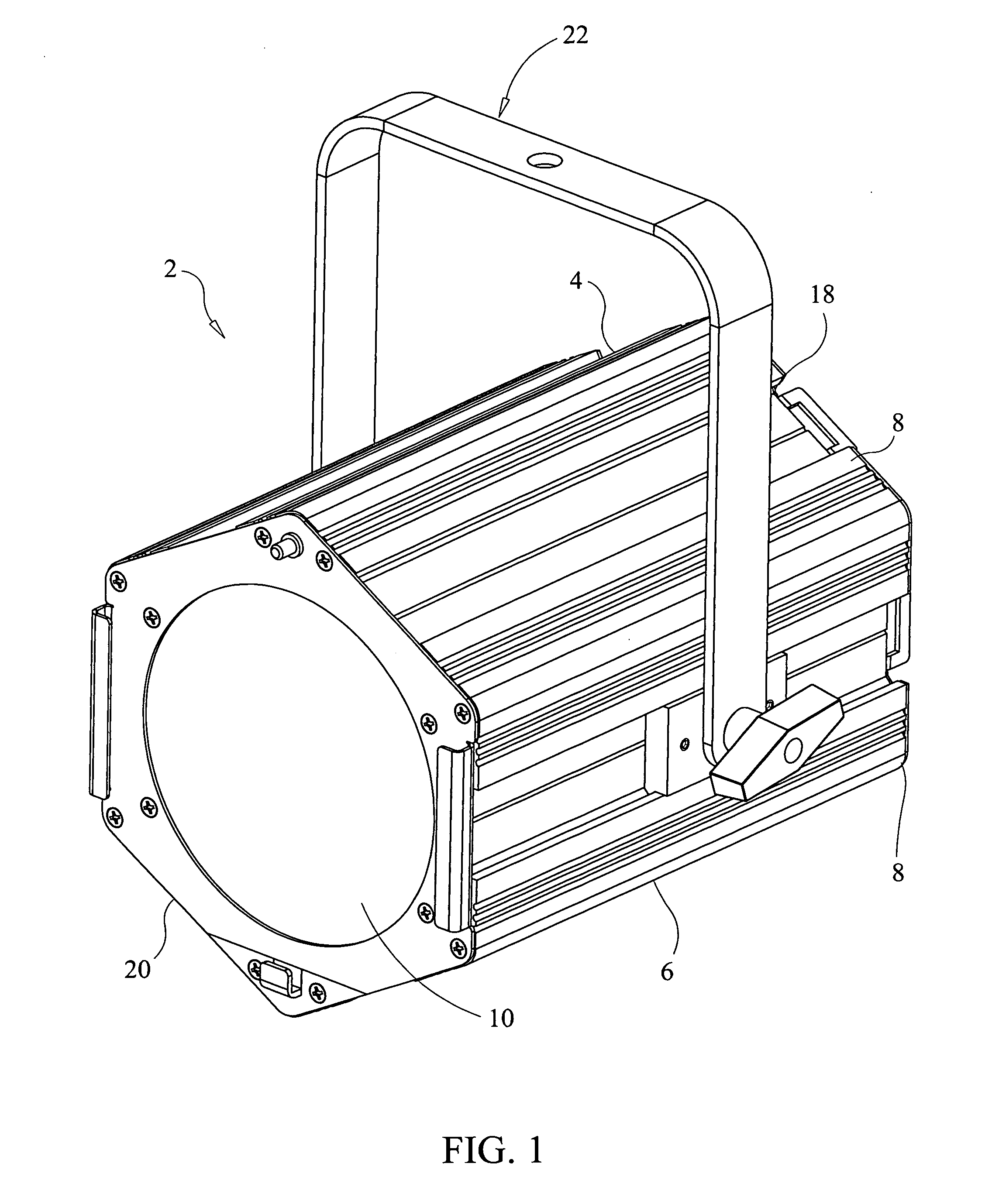
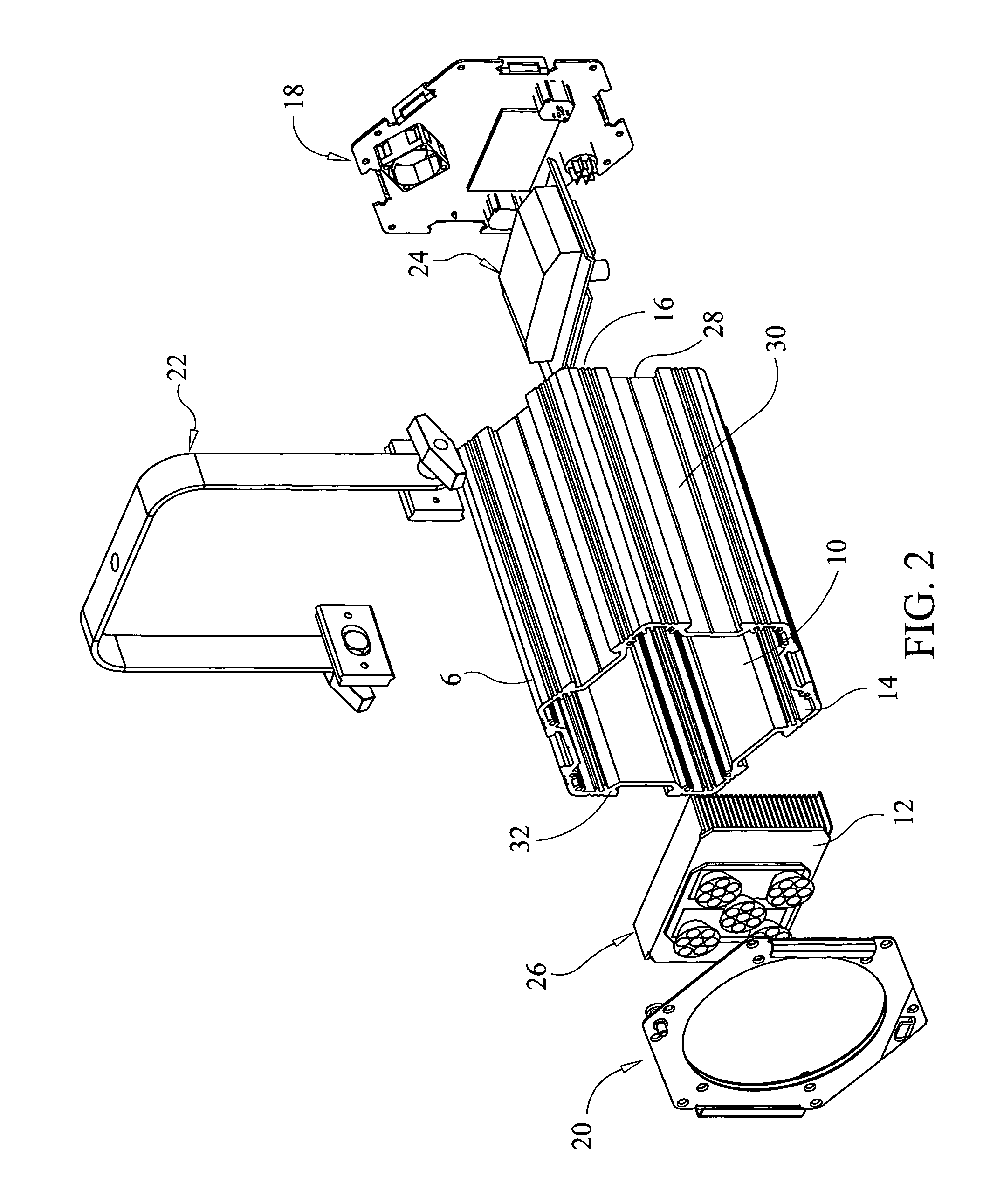
[0053]Referring initially to FIGS. 1 and 2 of the drawings (reference may also be had to FIGS. 13-20), it will be seen that an interlocking lighting fixture 2 constructed in accordance with the present invention includes a housing 4 having a polygonally-shaped main body 6 that includes a plurality of interconnected, generally planar side walls 8 situated about the periphery thereof. The main body 6 of the housing 4 is preferably hexagonal in shape in transverse cross-section, but it is envisioned to be within the scope of the present invention to form the housing with any number of side walls 8, such as three or more, as long as the transverse width of each side wall is sufficient to accommodate its interconnection to a corresponding side wall of a similarly shaped lighting fixture 2.

[0054]The main body 6 of the housing defines an interior space or cavity 10 for receiving one or more light emitting devices 12 and electronic circuitry for controlling the illumination of the light emi...


PUM


Abstract

A lighting fixture includes a hexagonal housing having six side walls. Each side wall has a slot formed therein. Two or more lighting fixtures may be joined together to form a modular arrangement of lighting fixtures in a plurality of configurations by using an interlock piece which slides into channels formed in facing side walls of adjacent lighting fixtures to hold the lighting fixtures together.

Description

CROSS-REFERENCE TO RELATED APPLICATIONS[0001]This application is related to U.S. Provisional Application Ser. No. 61 / 551,505, filed on Oct. 26, 2011, and entitled “Interlocking Lighting Fixture”, and U.S. Provisional Application Ser. No. 61 / 611,349, filed on Mar. 15, 2012, and also entitled “Interlocking Lighting Fixture”, the disclosure of each of which is incorporated herein by reference and on which priority is hereby claimed.BACKGROUND OF THE INVENTION[0002]1. Field of the Invention[0003]The present invention generally relates to lighting fixtures, and more specifically relates to lighting fixtures used for commercial, industrial and stage lighting.[0004]2. Description of the Prior Art[0005]Certain lighting fixtures used for commercial, industrial or stage lighting are generally stand-alone products which are individually suspended from a ceiling or mounted to a wall or floor. Each fixture must be individually directed or aimed to illuminate a desired object. Even if such conven...

Claims


Application Information

Patent Timeline
Patent Type & Authority Patents(United States)
IPC IPC(8): F21S8/00F21S2/00F21V5/04F21V21/00F21V21/005F21V21/30F21V23/04F21V29/00F21W131/40F21W131/406F21Y101/02F21Y105/00
CPCF21V21/00F21S2/005F21V21/005F21V21/30F21V5/04F21V29/004F21V29/02F21V23/04F21W2131/40F21W2131/406F21Y2101/02F21Y2105/001F21V29/763F21V29/74F21Y2105/10F21Y2115/10
Inventor LAVIGNA, DAVIDTEMPLE, ROBERT T.
Owner 0ENERGY LIGHTING
Why Eureka
Try Eureka