Electronically-controlled, high pressure flow control valve and method of use

a flow control valve, electric control technology, applied in the direction of valves, mechanical equipment, operating means/releasing devices, etc., can solve the problems of limited effective and safe aerosol delivery of pharmaceuticals to the lungs, low flow rate of valves used to control high pressure fluid flow, and inability to accept new drug applications

Active Publication Date: 2015-04-21
AEROPHASE
View PDF24 Cites 7 Cited by
  • Summary
  • Abstract
  • Description
  • Claims
  • Application Information

AI Technical Summary

Problems solved by technology

Effective and safe aerosol delivery of pharmaceuticals to the lungs is limited by the solvents and propellants that can be used in inhalers.
The US FDA will not accept new drug applications for any MDI formulations that use CFCs as propellants.
Valves used to control high pressure fluid flow at low flow rates are problematic.
Unfortunately, pMDIs based on prior art have several problems and drawbacks.
Such an approach has the problem that the movable chamber used to capture the aliquot is of fixed volume, so that the delivered drug amount is subject to change as the density of the propellant changes due to temperature changes, number of doses already administered from the canister, or other means.
Plus, even under ideal temperature storage conditions, the dose size is fixed, and cannot be adjusted.

Method used


Image

  • Electronically-controlled, high pressure flow control valve and method of use
  • Electronically-controlled, high pressure flow control valve and method of use
  • Electronically-controlled, high pressure flow control valve and method of use

Examples


example 1

[0138]A valve according to FIG. 5 is constructed and mounted onto an aluminum canister pressure vessel with an internal volume of 12 mL, incorporating a shape memory alloy actuator wire conductively mounted to an electrically-conductive standoff inside the canister, and a gold-plated metal pin as the sealing element seated against an elastomeric seat. The canister is pressurized to about 900 psi with carbon dioxide, and metered releases of carbon dioxide gas are effected by application of sufficient current to the shape memory alloy wire to cause it to contract and pull the pin away from the seat. After each release of pressurized gas from the canister into room pressure, after stopping the application of DC current to the shape memory alloy wire actuator, the pin returns to the closed position against the seat and the flow stops. The process is repeated several times. Finally, after pressurizing the canister with 2.88 g of carbon dioxide and sealing the canister with the aforementi...

example 2

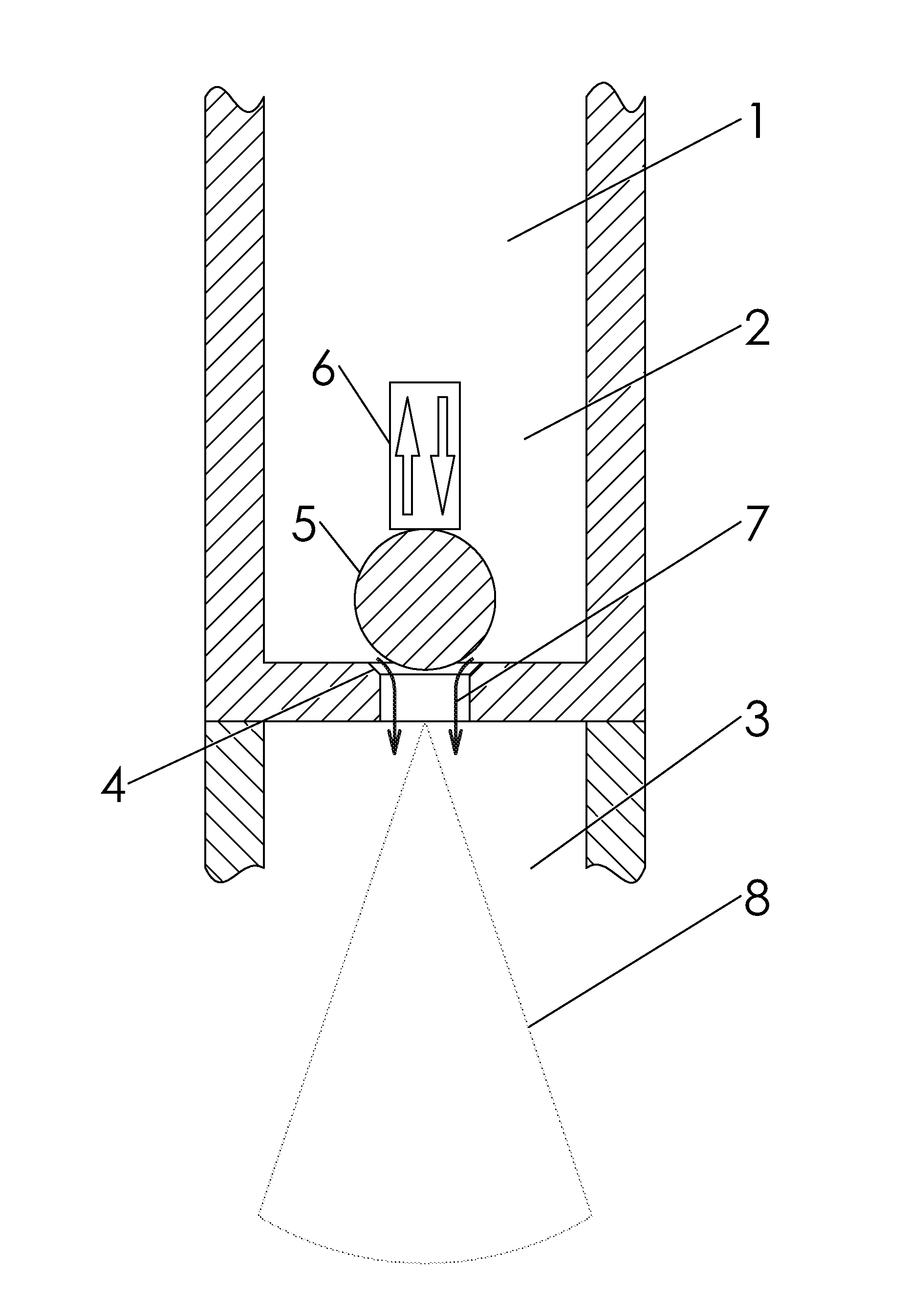
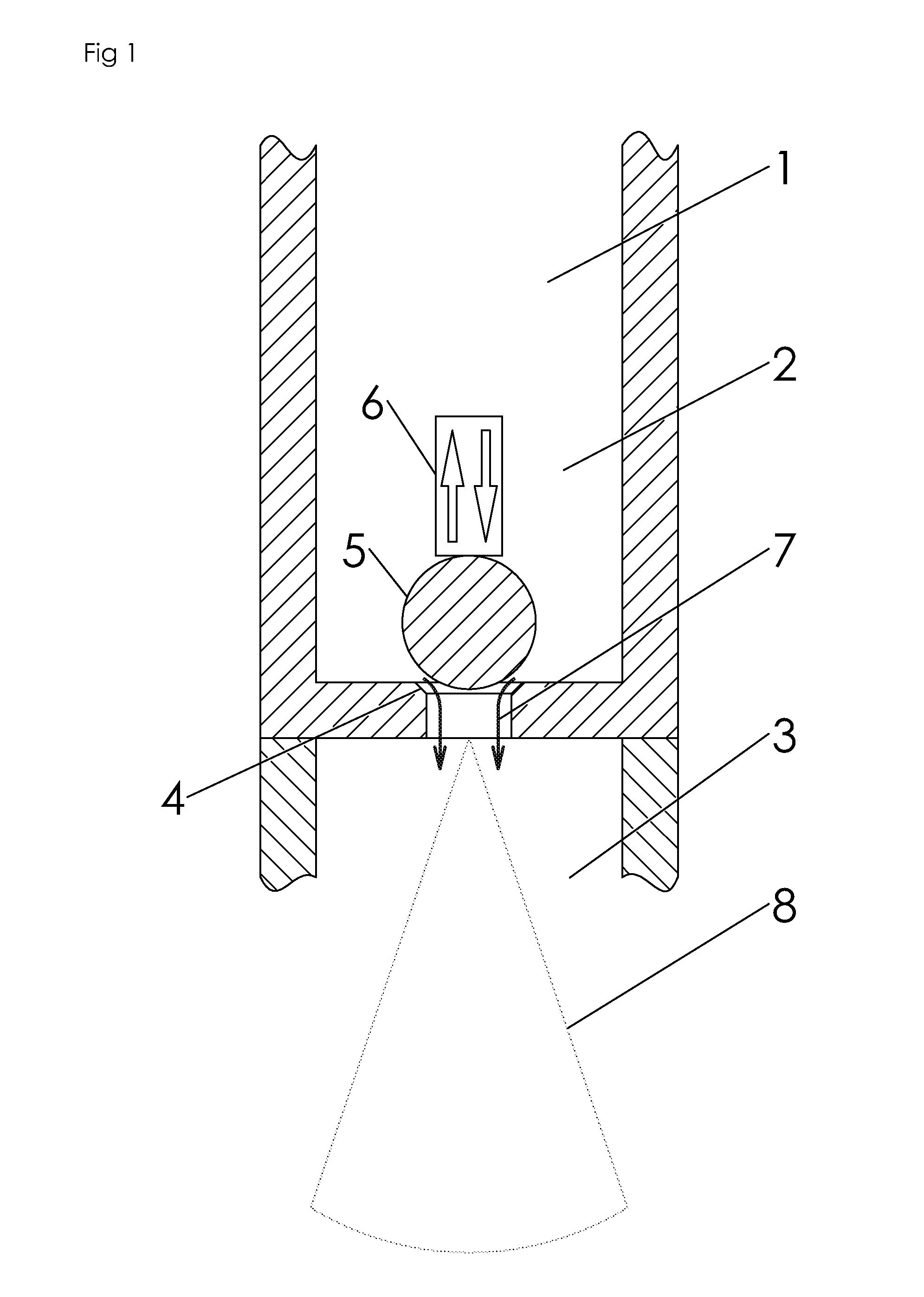
[0139]A valve according to FIG. 11 is constructed so that the metal ball sealing element, 1 mm diameter, is seated into the end of a 1.6 mm outer diameter stainless steel tube into which an internal beveled edge had been cut to facilitate seating of the ball against the tube. The ball is pressed into place with a U-shaped bimetal strip, preloaded with enough tension to hold the ball sealed against the tube when 2000 psi of pressure is applied inside the tube, and 2000 psi is maintained going into the tube with carbon dioxide. When current is passed through the bimetal strip, it bends away from the tube, sufficiently to allow the ball to move away from the tube and allow carbon dioxide to flow out of the tube into room pressure. It is determined that the flow rate is proportional to the amount of electrical current passed though the bimetal strip, and the valve is demonstrated to open and close through dozens of cycles of applying electrical current.

example 3

[0140]A valve according to FIG. 15 is constructed using a 0.4 mm OD tube through which flow is controlled from a region of 900 psi carbon dioxide to room pressure. A thin layer of polyurethane, approximately 0.2 mm thick, is applied to the surface of a 20 mm diameter brass disk on the opposite side from piezoelectric ceramic material conductively attached to the disk, also known as a piezoelectric bender. The disk is mounted perpendicular to the tube with the urethane coating pressed against the end of the tube with sufficient force to seal the tube against flow of the 900 psi carbon dioxide into the room pressure region. Eighty volts DC are applied to the piezoelectric bender, along with 6 kHz oscillating voltage, which bends the disk away from the tube and allows carbon dioxide flow to exit the tube. This actuation is repeatedly tested for 2500 on / off cycles of 0.8 sec on and about 7 sec off, and the valve is found to repeatedly release metered pulses of carbon dioxide gas and the...


PUM


Abstract

A fluid flow control valve comprises (a) a high pressure region adapted to contain a fluid at its supercritical or nearcritical temperature and pressure conditions and connected via an orifice to a low pressure region, (b) a seat adjacent the orifice, (c) a sealing element positionable against the seat to form a seal between the high pressure region and the low pressure region, and (d) an electrically and / or electronically controlled actuator operable to move the sealing element against and / or away from the seat to allow control of fluid flow from the high pressure region to the low pressure region. In a specific embodiment, the high pressure region contains a fluid at its supercritical or nearcritical temperature and pressure conditions. The valve may be used, for example, to provide very low flow rates, for example, for supercritical fluid chromatography, supercritical fluid extraction, critical point drying, supercritical fluid cleaning, and supercritical fluid separation methods. In another embodiment, the valve is suitable for use in methods of delivering a biologically active substance to a patient in need thereof.

Description

RELATED APPLICATIONS[0001]The present application claims priority under 35 U.S.C. §119 of U.S. Application Ser. No. 61 / 151,393 filed Feb. 10, 2009.STATEMENT REGARDING FEDERALLY SPONSORED RESEARCH AND DEVELOPMENT[0002]The present invention was partially made with Government support under grant R44HL066830 awarded by the US National Heart Lung and Blood Institute and R44CA096409 awarded by the US National Cancer Institute, National Institutes of Health. The Government has certain rights in the invention.FIELD OF THE INVENTION[0003]The present invention relates to methods and apparatus for high pressure fluid flow control. In more specific embodiments, the present invention relates to an improved, propellant-driven medical inhaler device for producing respirable aerosols of biologically-active substances, and to methods of using such devices. In further embodiments, the invention relates to electronically-controlled high pressure fluid flow valves and to devices and methods employing s...

Claims


Application Information

Patent Timeline
Patent Type & Authority Patents(United States)
IPC IPC(8): A62B9/02A61M11/00A61M15/00A61M16/00B65D83/54F16K1/14F16K31/02
CPCF16K31/02A61M15/009F16K1/14A61M15/008A61M2016/0021A61M2202/0225A61M2205/0266A61M2205/8225B65D83/54
Inventor HANSEN, BRIAN N.
Owner AEROPHASE
Why Eureka
Try Eureka