Subsea orientation and control system

a control system and subsea technology, applied in the direction of underwater equipment, surveying, borehole/well accessories, etc., can solve the problems of increasing costs, time and equipment use is very expensive, and can be hugely expensiv

Active Publication Date: 2015-04-21
AKER SOLUTIONS AS
View PDF31 Cites 18 Cited by
  • Summary
  • Abstract
  • Description
  • Claims
  • Application Information

AI Technical Summary

Problems solved by technology

The time and equipment used is very expensive.
However, in deep water, which can be thousands of meters of depth, and with a large number of wellheads, the cost can be tremendous.
Sometimes the rig must return for further testing or installation, which adds to the costs.
The operation of joining drill pipes to lengths of up to several thousand meters, and large drums with umbilicals, installations for hydraulic power units, hydraulic liquid storage and gas for testing, are all expensive and time consuming.
The heavy weight and size require large space, and may require several containers on deck on the rig.

Method used


Image

  • Subsea orientation and control system
  • Subsea orientation and control system
  • Subsea orientation and control system

Examples


Embodiment Construction

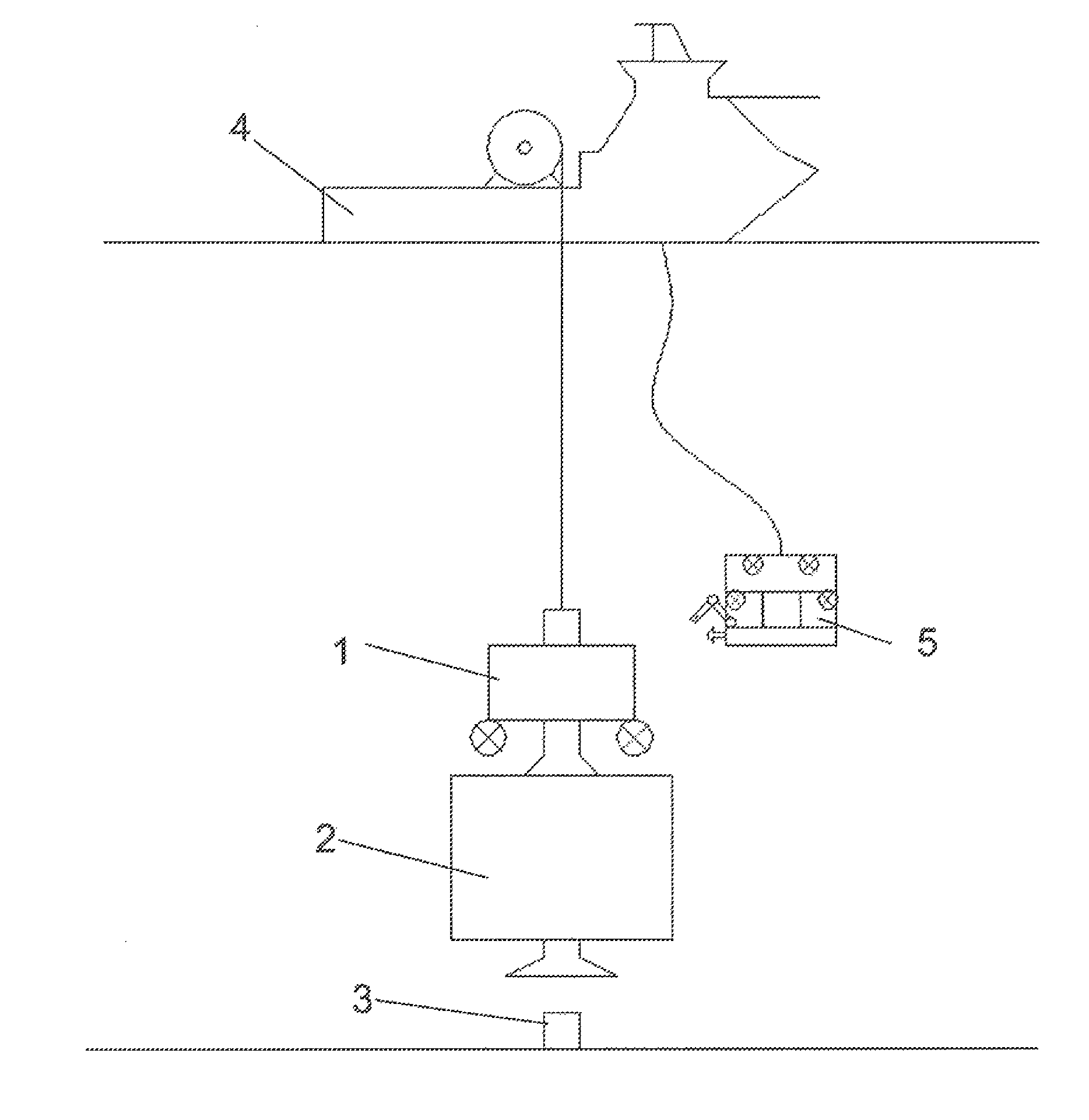
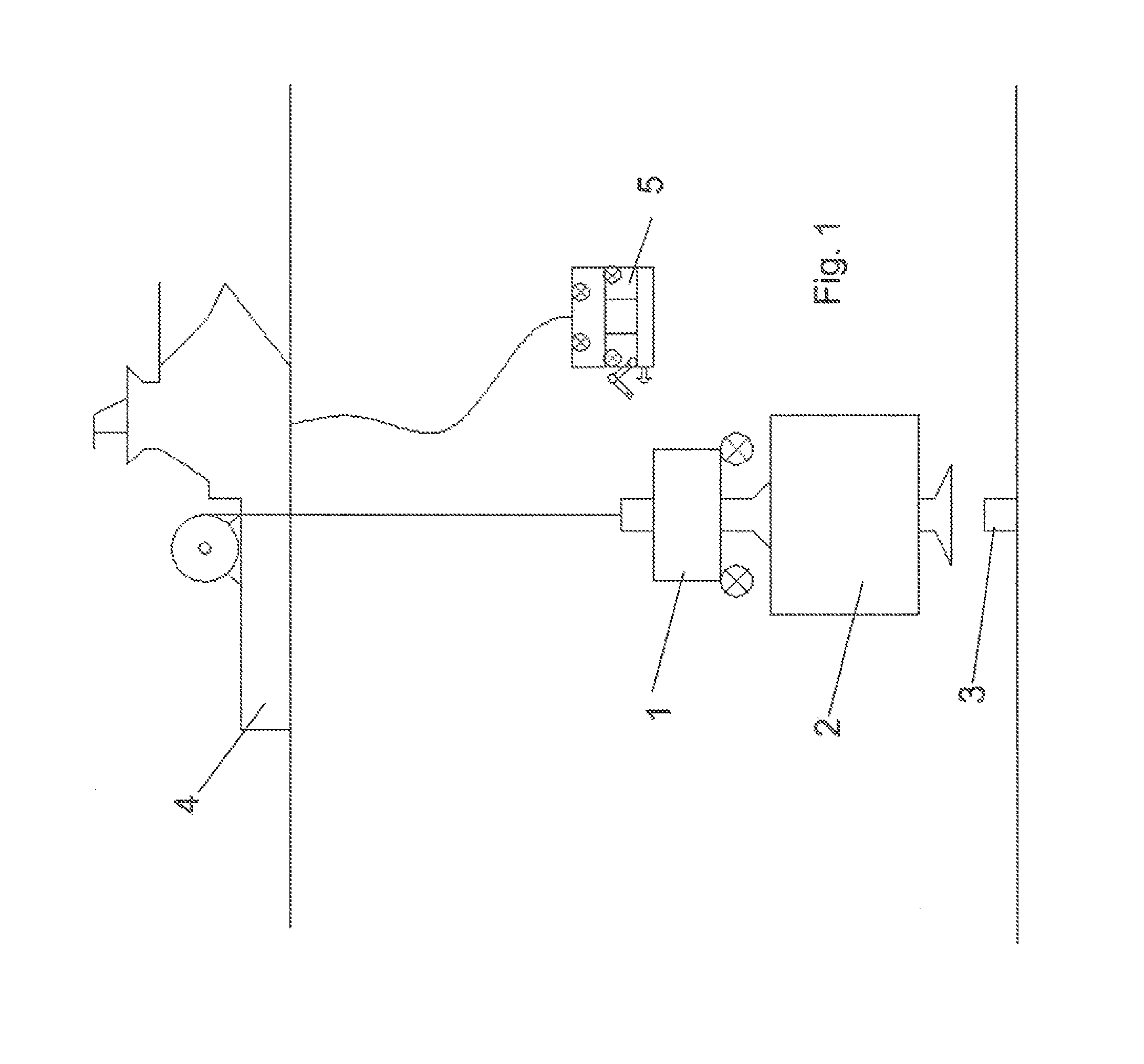
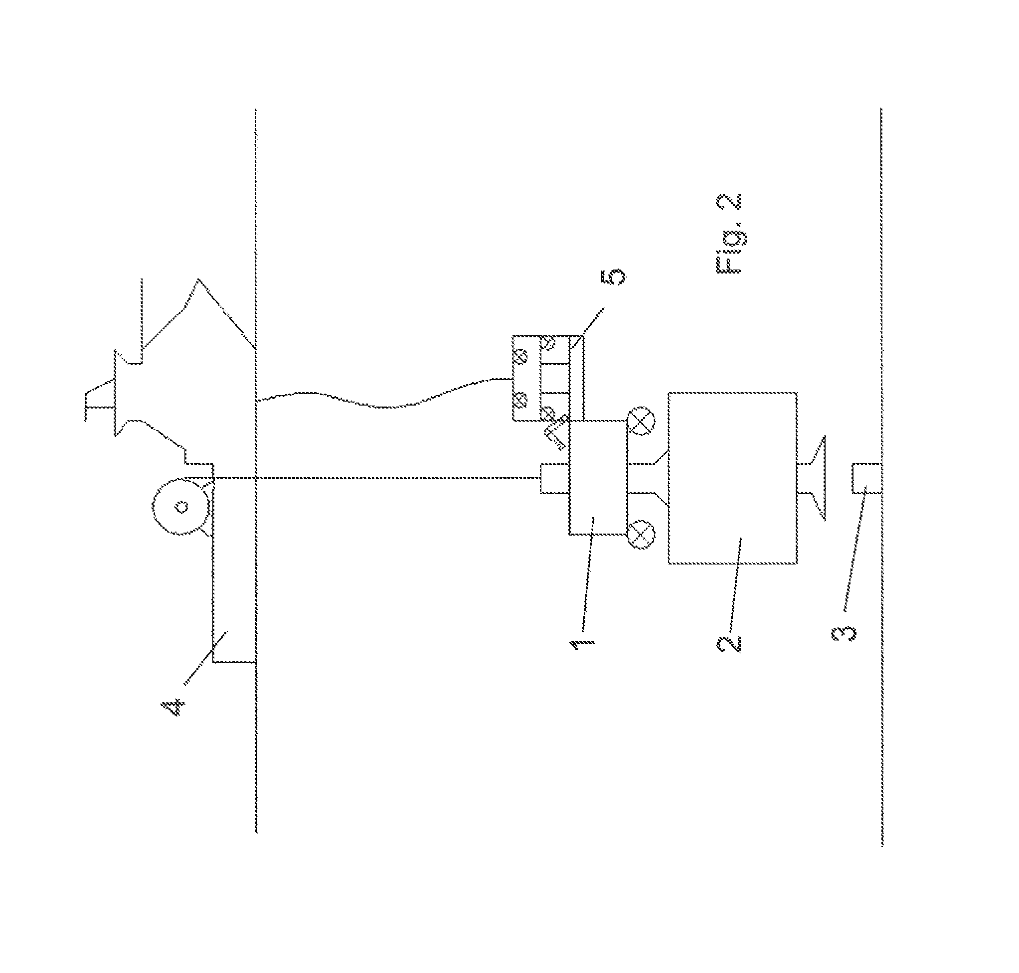
[0025]Reference is made to FIG. 1, illustrating a tool according to the invention, more specifically a subsea unit 1 of the tool, as releasably connected to a subsea x-mas tree 2, for connection to a subsea wellhead 3. The assembly is deployed as hanging from a ship 4. Also, a ROV 5 is illustrated, operated from the ship. Reference is then made to FIG. 2, illustrating that the ROV has docked to the subsea unit 1. In the illustrated embodiment, the assembly of the subsea unit 1 and the x-mas tree 2 hangs in a rope from the ship, and electric power and control signals are provided via the ROV, via the electrical-optical umbilical of the ROV, using the hydraulic power unit of the ROV for driving a hydraulic system of the subsea unit via a hydraulic converter pump. Alternatively, the subsea unit could be directly connected to a fluidless umbilical, the subsea unit per se including all means for operating and testing mechanical, electrical and any other devices, or the means could be pro...


PUM


Abstract

A tool for subsea installation and testing of wellhead modules such as Xmas trees and similar equipment, from a ship using a ship crane. The tool includes a subsea unit that includes a connector for releasable connection to subsea wellhead modules or equipment, means for positioning and means for testing, and a connector for electric power and electric and / or optical control.

Description

FIELD OF THE INVENTION[0001]The present invention relates to subsea wellhead stacks. More specifically, the invention relates to tools and methods for installation of wellhead stacks, such as wellhead XT (Christmas trees) and associated equipment.BACKGROUND OF THE INVENTION AND PRIOR ART[0002]Currently, subsea wellhead stacks are typically installed by using a drilling rig and a string of drillpipe for deployment. A separate umbilical from the rig to the wellhead equipment provides pressurized fluids for testing and commissioning, in addition to electric power and control lines. Typically one or more ROV's are also used in the operation. The time and equipment used is very expensive. In shallow waters, if the drilling rig is on the field and has commenced drilling and then is used to install a few production XT (Christmas trees) and other related equipment, this can be sensible, particularly if the drilling rig still is under contract. However, in deep water, which can be thousands ...

Claims


Application Information

Patent Timeline
Patent Type & Authority Patents(United States)
IPC IPC(8): E21B33/035E21B41/04E21B19/00E21B47/10
CPCE21B19/002E21B41/04E21B47/1025E21B47/117
Inventor BILLINGTON, ANDERSSYNNES, ARESOVIK, CHRISTEN
Owner AKER SOLUTIONS AS
Why Eureka
Try Eureka