Container with movable bottom plate

a technology of container and bottom plate, which is applied in the field of containers, can solve the problems of waste of products and difficulty for users to completely empty containers, and achieve the effect of reducing air volume and convenient and easy access to materials

Inactive Publication Date: 2015-04-28
LEIGHTON JOSEPH PAUL
View PDF15 Cites 19 Cited by
  • Summary
  • Abstract
  • Description
  • Claims
  • Application Information

AI Technical Summary

Benefits of technology

[0013]The container has a handle having a middle region that is useful for engaging a surface to help stabilize the container when the product is being dispensed.
[0014]Accordingly, among the objects of the instant invention are: the provision of a unique and novel container in which the bottom plate movable and slidably engages an interior surface of the container to facilitate convenient and easy access and removal of material from the container. Another object of the invention is to provide a container having a bottom plate that engages a ratcheting mechanism along the interior wall of the container so that the bottom plate can be supported at various heights within the container. Another object of the invention is to provide a container having a movable bottom plate for reducing the air volume within the container after some of a product has been dispensed from the container. Another object of the present invention is to provide a container that has vents that are separate from the dispensing opening, and independently sealable from the sealable dispensing opening, so that the dispensing aperture may be sealed to contain the dispensable product within the container while air is vented from the container.

Problems solved by technology

For products that dry when exposed to air, this can cause the product to dry entirely or partially within the bucket before the user is ready to use the product again, resulting in wasted product.
Additionally, when the bucket is deep, it will become difficult for a user to completely empty the container, as the last remnants of the product can be hard to reach at the bottom of the bucket.

Method used


Image

  • Container with movable bottom plate
  • Container with movable bottom plate
  • Container with movable bottom plate

Examples


Embodiment Construction

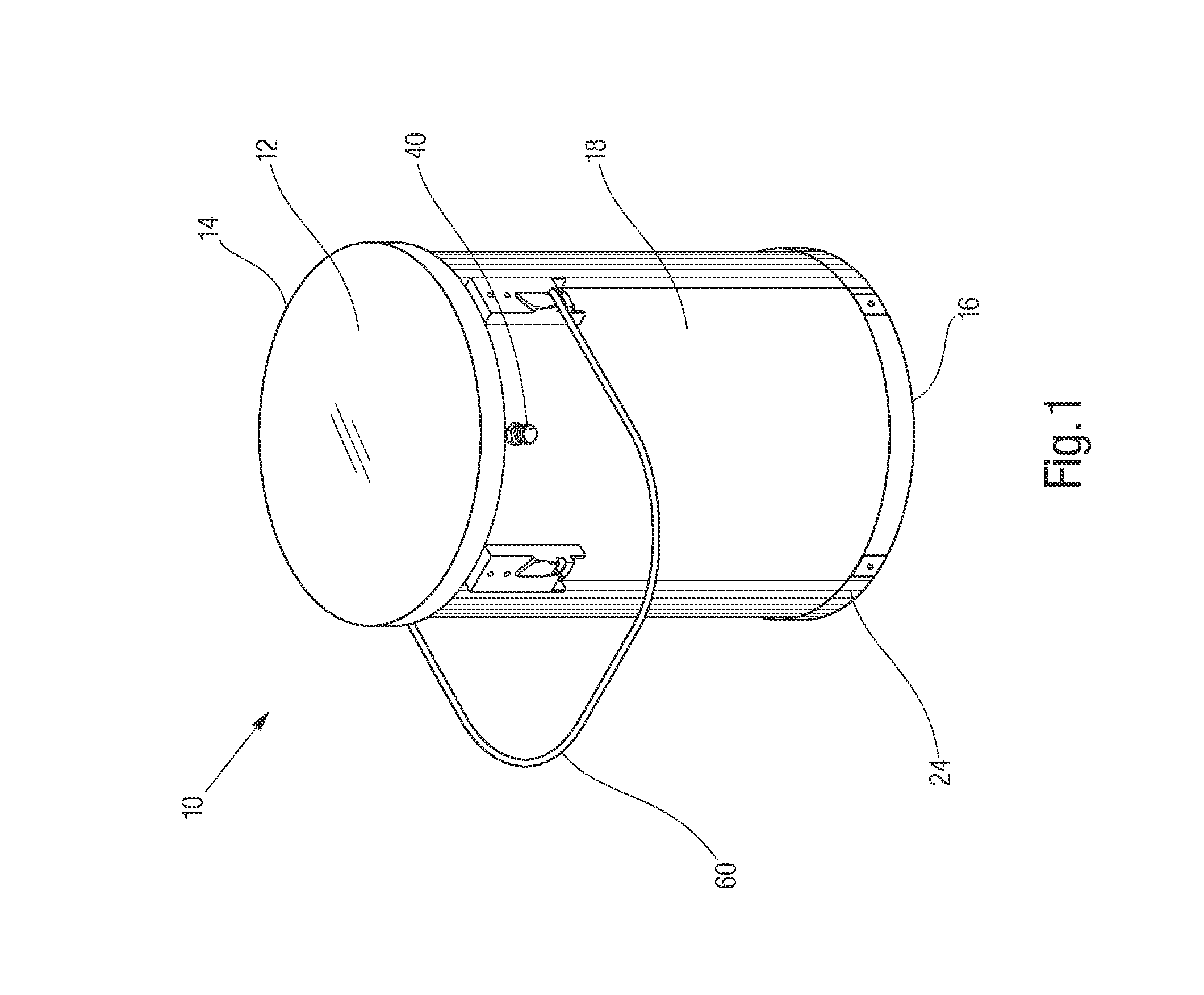
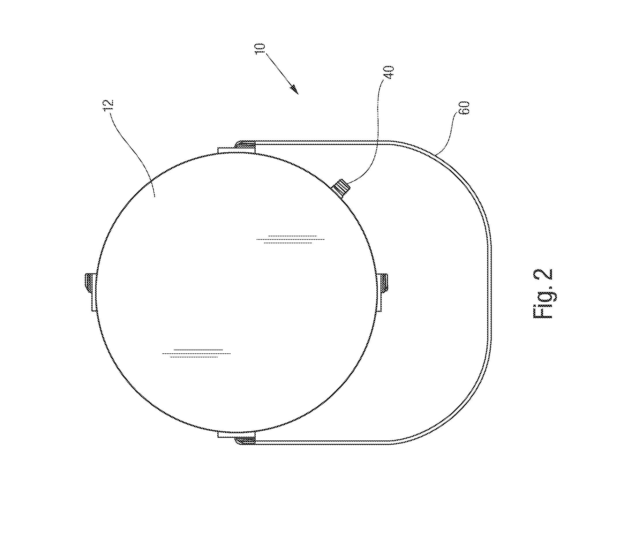
[0030]Referring now to the drawings, the container with movable bottom plate of the instant invention is illustrated and generally indicated at 10 in FIGS. 1-17. As will hereinafter be more fully described, the instant invention provides a container with a movable bottom plate for expelling air from the container and for making a product within the container more easily accessible.

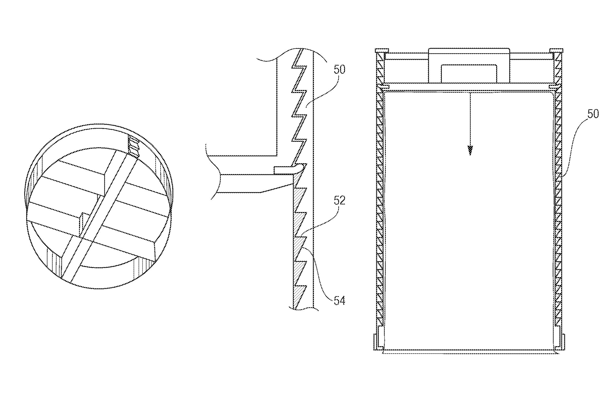
[0031]In FIGS. 1-17 there is shown the container with a movable bottom plate comprising a lower portion and an upper portion. The lower portion of the container includes a retaining ring for engaging a bottom plate before the bottom plate is moved towards an upper portion of the container.

[0032]As seen in FIGS. 1-6, the exemplary embodiment of the container 10 defines an overall cylindrical shape, but of course this is merely an example, and the container may define other shapes and sizes. In one embodiment, the shape of the container may be, for example, square or rectangular. Still further, the container...


PUM


Abstract

A container has a movable bottom plate to facilitate dispensing material from the container and accessing material remaining within the container. The container has an inner chamber, further having an upper inner chamber and a lower inner chamber. The bottom plate slidably engages the inner surface of the inner chamber. A user can reach a handle on the bottom plate through an aperture at the bottom end of the container. The bottom plate is a plunger that can be moved from a lower inner chamber of the container to an upper inner chamber to remove material from the container. The bottom plate can be moved from the lower end towards the upper end of the container to dispense a product or to expel air from the container through vents positioned on the bottom plate and on the container wall towards the upper end of the container.

Description

CROSS REFERENCE TO RELATED APPLICATION[0001]This application is related to and claims priority to earlier filed U.S. provisional patent application 61 / 722,583, filed Nov. 5, 2012, the entire contents of which are incorporated herein by reference.BACKGROUND[0002]The instant invention relates to containers for dispensing and storing a product. More particularly, the invention relates to containers for products that react with air.[0003]Various spreadable or flowable products, such as glue, grout or other construction materials, may be packaged in a sealable bucket. A user may wish to use only a small amount of the product at a time, and store the rest for later. In this situation, the user removes some product for use, and reseals the container. In a conventional container, air fills the void left by the removed material. For products that dry when exposed to air, this can cause the product to dry entirely or partially within the bucket before the user is ready to use the product agai...

Claims


Application Information

Patent Timeline
Patent Type & Authority Patents(United States)
IPC IPC(8): B65D6/16B65D25/06
CPCB65D11/18B65D25/06B65D25/04B65D81/245B65D83/0005
Inventor LEIGHTON, JOSEPH PAULDESMARAIS, RICHARD
Owner LEIGHTON JOSEPH PAUL
Why Eureka
Try Eureka