Distance estimation between a fiber end and a tissue using numerical aperture modulation

a technology of distance estimation and aperture modulation, applied in the field of optical fibers, can solve problems such as difficult measuremen

Active Publication Date: 2015-04-28
LUMENIS LTD
View PDF9 Cites 13 Cited by
  • Summary
  • Abstract
  • Description
  • Claims
  • Application Information

AI Technical Summary

Problems solved by technology

However these are very difficult to measure due to the permanent motion of the fiber and permanent changes in the treated tissue and its environment.

Method used


Image

  • Distance estimation between a fiber end and a tissue using numerical aperture modulation
  • Distance estimation between a fiber end and a tissue using numerical aperture modulation
  • Distance estimation between a fiber end and a tissue using numerical aperture modulation

Examples


Embodiment Construction

[0014]Prior to setting forth the detailed description, it may be helpful to set forth definitions of certain terms that will be used hereinafter.

[0015]The term “laser” as used herein in this application refers to any type of laser—For example solid state (e.g. Neodymium, Erbium, Holmium, Thulium or Alexandrite), diode (e.g. in various wavelengths, such as in the range 532-1600 nm), gas (e.g. CO2, Argon) or fiber laser (e.g. Neodymium, Erbium, Holmium, Thulium or Alexandrite). Furthermore, laser beams referred to in the application may be continuous, pulsed, Q-switched, or any other temporal pattern.

[0016]The term “treatment beam” as used herein in this application refers to an intense laser beam transferred through an optical fiber to treat a target tissue. For example, treatment beam may be a pulsed laser beam or any other laser beam as defined above. The treatment may be ablative or non-ablative, as determined by the beam intensity in respect to a tissue ablation threshold of appr...


PUM


Abstract

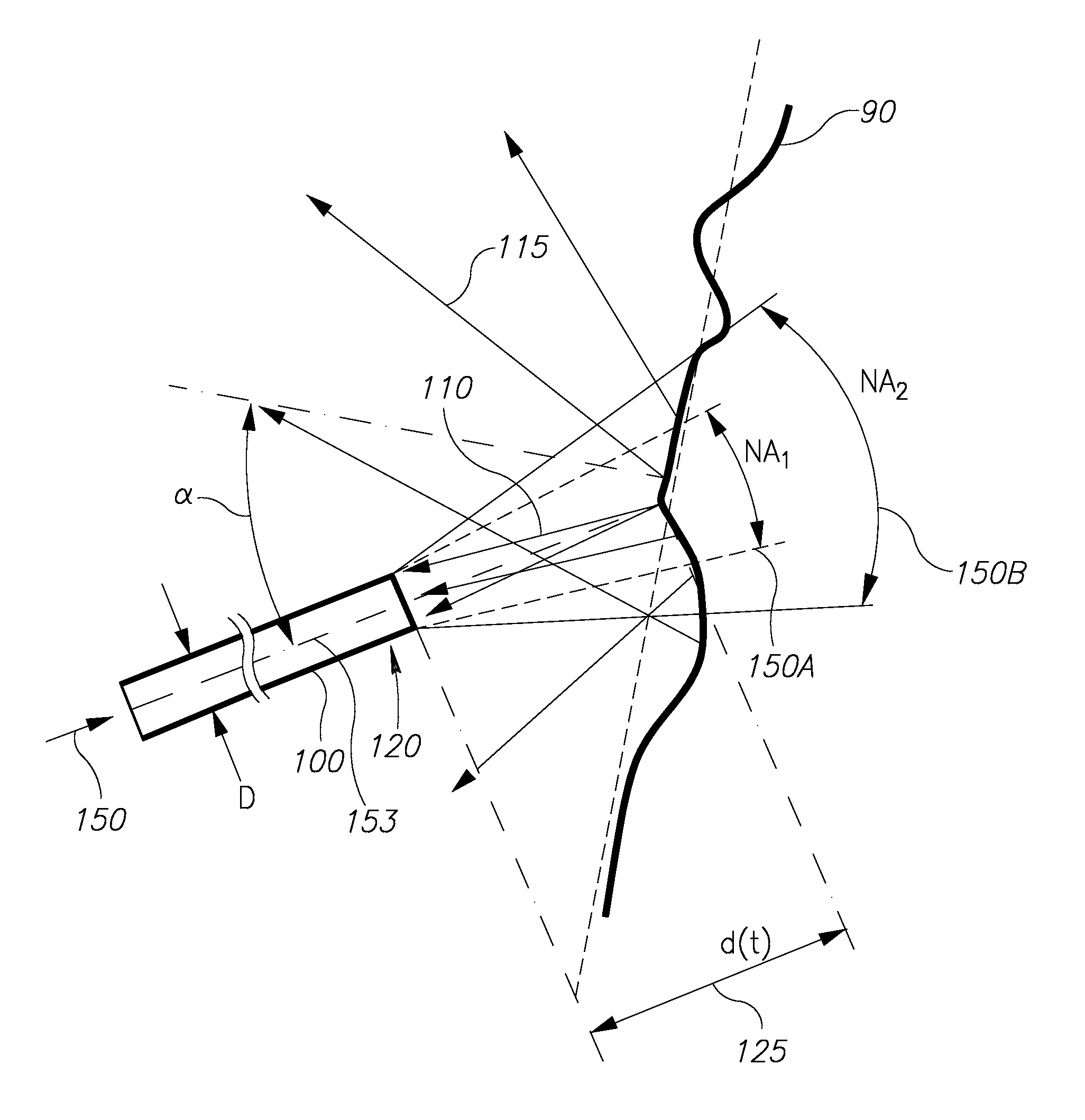
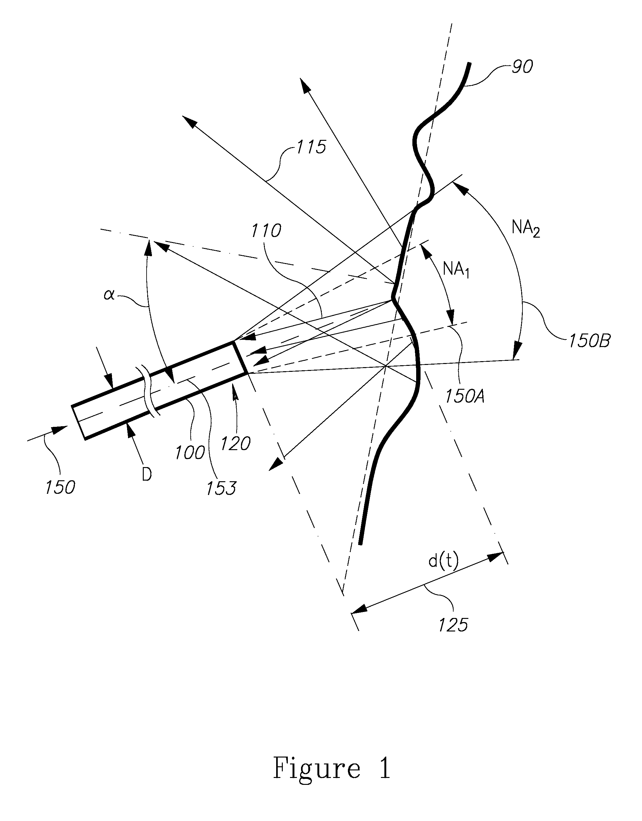
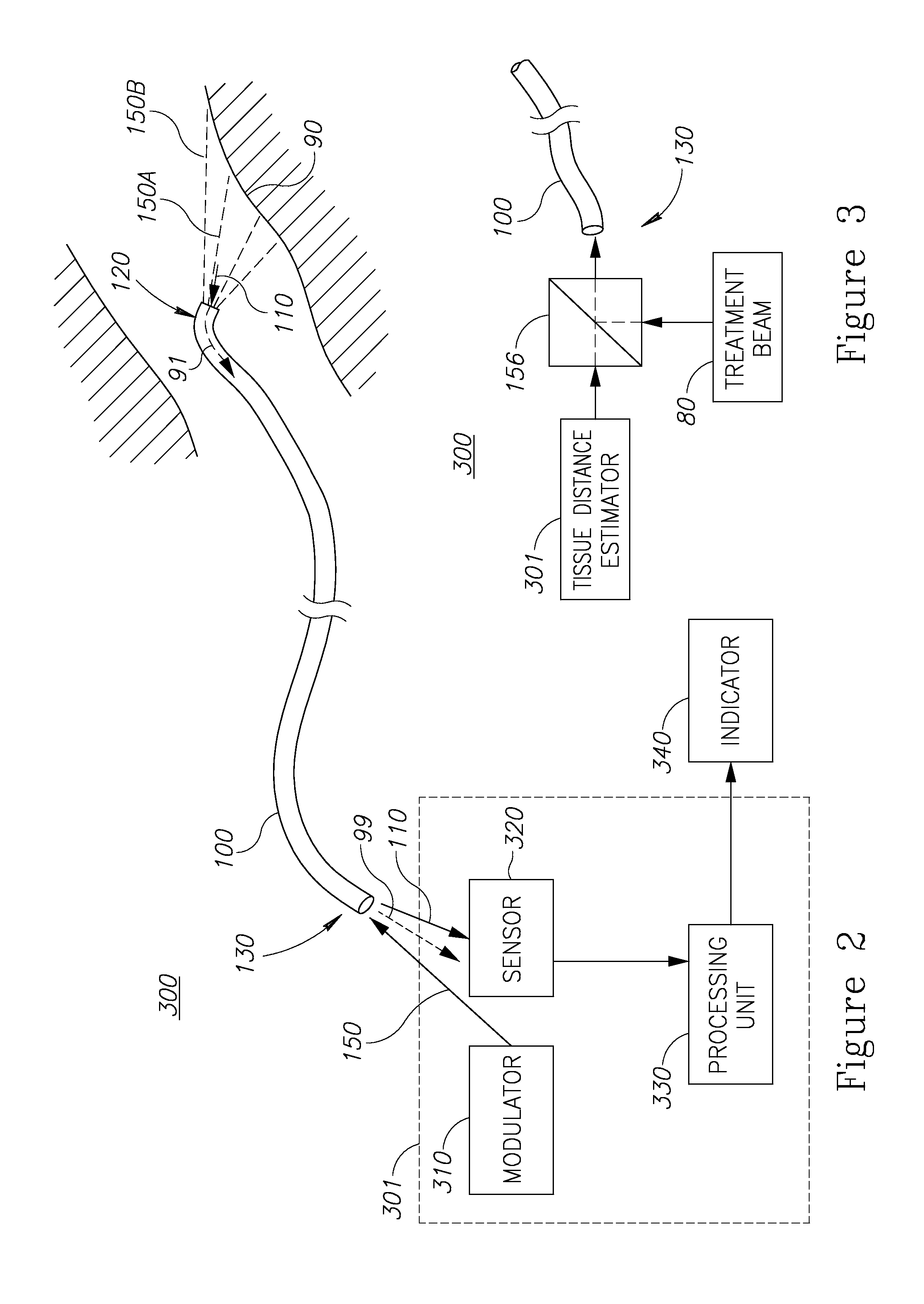
A system and method of estimating a distance between the distal end of an optical fiber and treated tissue, to improve treatment efficiency, is provided herein. The estimation is achieved by modulating the numerical aperture of a light beam transmitted through the fiber to receive reflections from the tissue and distinguish them from other reflections in the fiber, and further by calculating the distance by comparing reflection intensities of beams having different numerical aperture values that illuminate the tissue over a very short period, so that tissue and environment conditions do not change much. Distance estimation may be carried out by modulating the treatment beam itself, or by a light beam transmitted between pulses of a pulsed treatment beam.

Description

BACKGROUND[0001]1. Technical Field[0002]The present invention relates to optical fibers and more particularly, to laser treatment devices.[0003]2. Discussion of the Related Art[0004]Many non-invasive or minimally invasive treatment methods involve delivering energy to a tissue by irradiating the tissue with a laser beam through an optical fiber. Treatment efficiency depends strongly on the relative position and orientation of the fiber tip in respect to the tissue. However these are very difficult to measure due to the permanent motion of the fiber and permanent changes in the treated tissue and its environment. Hence, currently physicians are in the dark regarding the location of the fiber tip in respect to the treated tissue.BRIEF SUMMARY[0005]One aspect of the invention provides a method comprising: modulating a numerical aperture of a light beam transmitted through an optical fiber and directed at a target tissue via a distal end of the optical fiber, measuring intensity values ...

Claims


Application Information

Patent Timeline
Patent Type & Authority Patents(United States)
IPC IPC(8): A61B18/22A61B17/00A61N5/06G01B11/02
CPCA61B18/22A61N5/0601G01B11/026A61N5/06A61B2017/00066A61B2018/2244A61N2005/063A61B2018/2253A61B2018/00785
Inventor KHATCHATUROV, ARKADYVOITSECHOV, URIKOIFMAN, IGAL
Owner LUMENIS LTD
Why Eureka
Try Eureka