Fly-in landing pad for lift-fan aircraft

a technology for liftfan aircraft and landing pads, which is applied in the direction of vertical landing/take-off aircraft, aircraft navigation control, transportation and packaging, etc. it can solve problems such as damage or injury, achieve steady increase in width, facilitate rolling and unrolling, and reduce the effect of downdraft air velocity

Inactive Publication Date: 2015-05-05
KOSHELEFF PATRICK A
View PDF34 Cites 58 Cited by
  • Summary
  • Abstract
  • Description
  • Claims
  • Application Information

AI Technical Summary

Benefits of technology

[0007]An airplane capable of a vertical landing brings a portable landing pad in a compact state. The landing pad has a deformable flat surface which will be deployed along the ground for use by subsequent lift-fan VTOL airplanes. The compact state makes the landing pad air-transportable. Compact state is attained before flight by rolling up the deformable surface.
[0008]The preferred embodiment of the deformable surface is many long slats each flexibly joined to two adjacent slats at the long edges. This is excepting the two end slats, which connect only once. One end slat is hinged to a base plate which supports the weight of the rolled-up pad. The other end slat will be the center slat. It has stub shafts sticking out its lengthwise ends to facilitate the rolling and unrolling. Rolling up the slats before takeoff achieves the compact state. The slats are fabricated with steadily increasing widths. Then the slats can wind up to make a tight spiral roll. Unrolling after landing is the reverse operation. Unrolling can be done by two husky men pushing on six-foot wheels, each one slipped over one end of the stub shafts first.
[0009]An upturned wall at the end of the deployed landing pad deflects upward the blast of air from landing VTOL airplanes. These create a downdraft air velocity much greater than with helicopters. Small debris on the ground are picked up and hurled outward, possibly causing damage or injury. The upturned wall creates a “shadow zone” free from the windblast. The landing pad itself keeps the debris on the ground. Thus, massed operations using many lift-fan VTOL airplanes can be conducted safely.

Problems solved by technology

Small debris on the ground are picked up and hurled outward, possibly causing damage or injury.

Method used


Image

  • Fly-in landing pad for lift-fan aircraft
  • Fly-in landing pad for lift-fan aircraft
  • Fly-in landing pad for lift-fan aircraft

Examples


Embodiment Construction

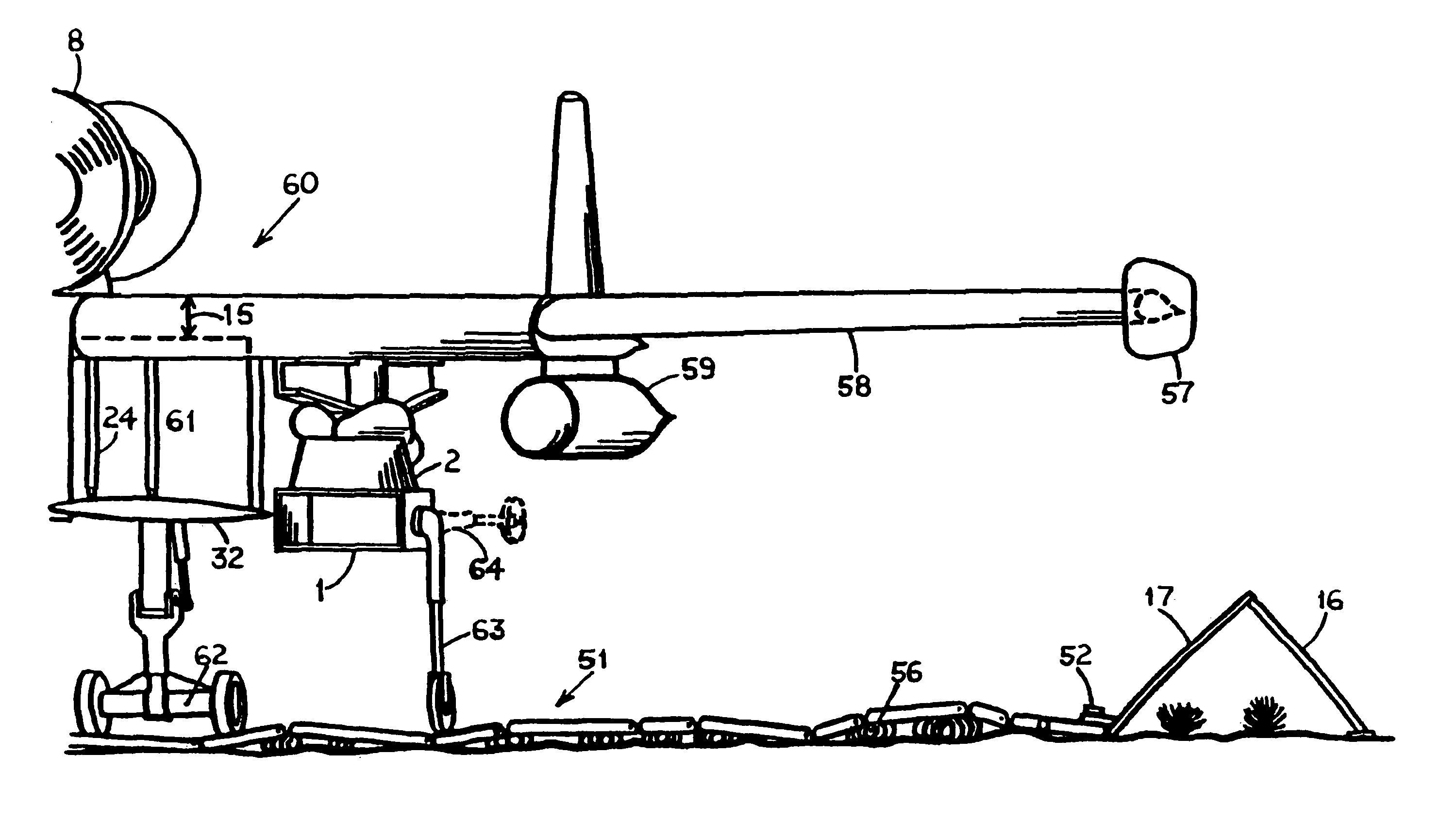
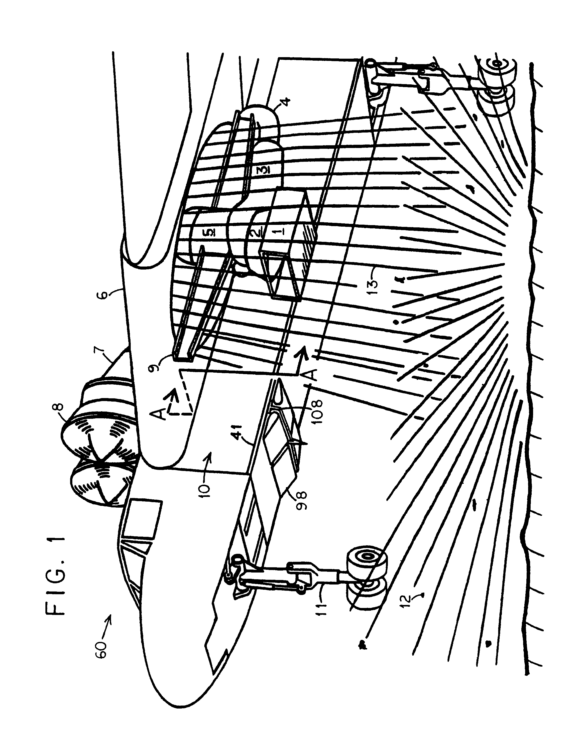
[0030]Vertical Take-Off and Landing (“VTOL”) airplanes are known. The V-22 “Osprey” tilt-rotor airplane is the latest example. The present invention concerns VTOL airplanes bf the lift-fan type. These have smaller rotors which turn quite fast. The air downflow 13 in FIG. 1 which creates lift is faster too. When lift-fan airplanes land on ordinary ground, they kick up dirt or pebbles 12 which can attain high speeds. Damage to property or injury to people can result. The invention aims to reduce that hazard.

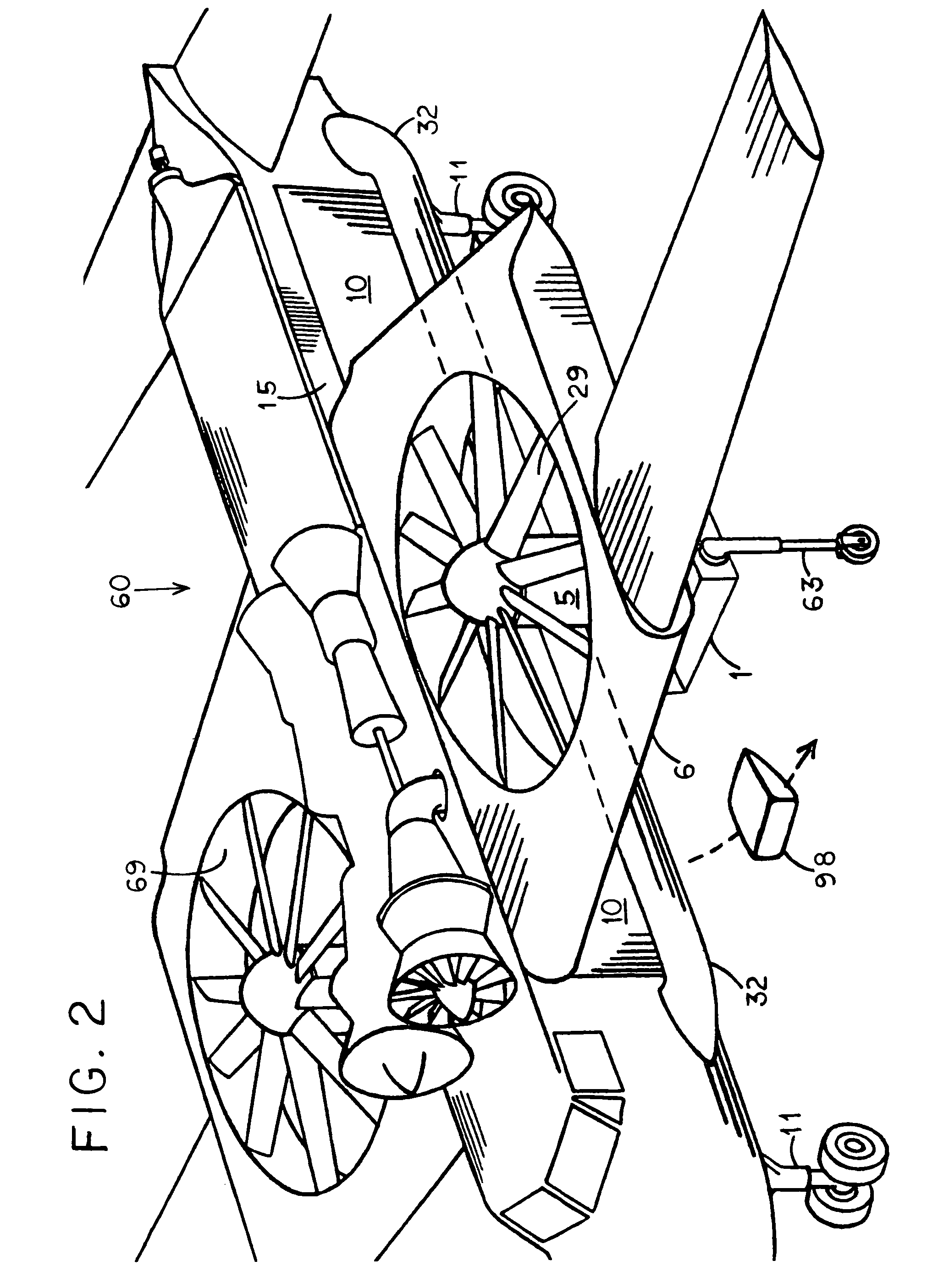
[0031]In FIG. 1, lift-fan airplane 60 is medium-sized, with a wingspan of 90 feet and able to carry a payload of 10,000 lbs. Airplane 60 is a cargo plane. Its cargo load 10 is a rolled-up landing pad for subsequent lift-fan airplanes to land on.

[0032]The best-known VTOL aircraft are helicopters, which have large rotors. The UH-60A “Blackhawk” can carry 16 people and its rotor diameter is 53½ feet. Large, slow-turning rotors are most efficient to create vertical lift. A desire to ac...


PUM


Abstract

A lift-fan airplane lands vertically on dirt, kicking up debris but bringing a landing pad for use by others. The landing pad comprises many long slats hinged to each other at the sides. The slats are of generally increasing widths for rolling up into a tight spiral. This compact state allows low-drag air transport. After landing, the spiral is unrolled. A central slat has two stub axles sticking out the ends. Two men place a large wheel onto each stub axle, then push on the wheels to unroll the landing pad on the ground. An upturned wall at the end of the pad deflects upward the downwash from landing lift-fan VTOL airplanes, creating a shadow zone free of flying debris. This creates safe parking for massed operations. Inflated balloons, wedge-shaped to streamline necessary protuberances, detach and fill any large potholes under the landing pad.

Description

BACKGROUND OF THE INVENTION[0001]A VTOL airplane brings a landing pad in the compact state. The landing pad was rolled up for flight, but after landing it unrolls on the ground, to support the landing of subsequent lift-fan airplanes.[0002]U.S. Pat. No. 3,456,909 brings a rolled-up carpet hanging under a helicopter. Unrolling at the desired landing site creates the landing pad for subsequent helicopters. Our rolling configuration is different.[0003]U.S. Pat. No. 3,649,724 in its preliminary discussion cites prior art wherein a mat is rolled or otherwise compacted to a readily transportable state, then transported and dropped on the ground. Personnel on the ground may complete the deployment. We duplicate all these actions, but our compact state is more specific.[0004]U.S. Pat. No. 2,371,017 shows a transportable mat which includes transverse bands 13 (which are) “in effect a relatively stiff panel.” This resembles our landing pad made up of individual slats. The resemblance is carri...

Claims


Application Information

Patent Timeline
Patent Type & Authority Patents(United States)
IPC IPC(8): B64F1/00B64F1/26
CPCB64F1/007B64F1/00B64F1/26
Inventor KOSHELEFF, PATRICK A.
Owner KOSHELEFF PATRICK A
Why Eureka
Try Eureka