A structure for the reinforcement of pavements comprising assemblies of grouped metal filaments coupled to or integrated in a substrate

a technology of metal filaments and assemblies, applied in the direction of single unit pavings, knitting, ways, etc., can solve the problems of reducing the overall serviceability of pavements, deteriorating pavement structures, and reflecting cracks, and achieves the effect of high structure flexibility and easy rolling up and unrolling

Active Publication Date: 2016-01-14
NV BEKAERT SA
View PDF13 Cites 0 Cited by
  • Summary
  • Abstract
  • Description
  • Claims
  • Application Information

AI Technical Summary

Benefits of technology

[0102]Thanks to the high flexibility of the structure for the reinforcement of pavements, the structure can easily be rolled up and unrolled. This is making the use on the construction site easy.
[0103]By installing a structure for the reinforcement of pavements according to the present invention, the reflective cracking from a distressed and cracked road surface to a newly applied overlay is avoided or at least retarded.

Problems solved by technology

A serious drawback of this method includes reflective cracking.
Left untreated, this situation will lead to further deterioration of the pavement structure and to a reduction in overall serviceability.
Although it has been proven that steel meshes such as hexagonal woven meshes, are successful to reduce cracking in the overlay, steel meshes have the drawback that the installation is difficult due to the rigid nature of such steel meshes.
A further drawback of the use of steel meshes is that thick overlay layers of for example 8 cm or more are required in order to be efficient.
Polymer material and glass material have a limited strength.
Furthermore, polymer material can lose its integrity due to the high temperature of the asphalt during installation (160° C.).
Glass can get damaged during its installation due to its brittle nature and requires additional protection.

Method used


Image

  • A structure for the reinforcement of pavements comprising assemblies of grouped metal filaments coupled to or integrated in a substrate
  • A structure for the reinforcement of pavements comprising assemblies of grouped metal filaments coupled to or integrated in a substrate
  • A structure for the reinforcement of pavements comprising assemblies of grouped metal filaments coupled to or integrated in a substrate

Examples


first embodiment

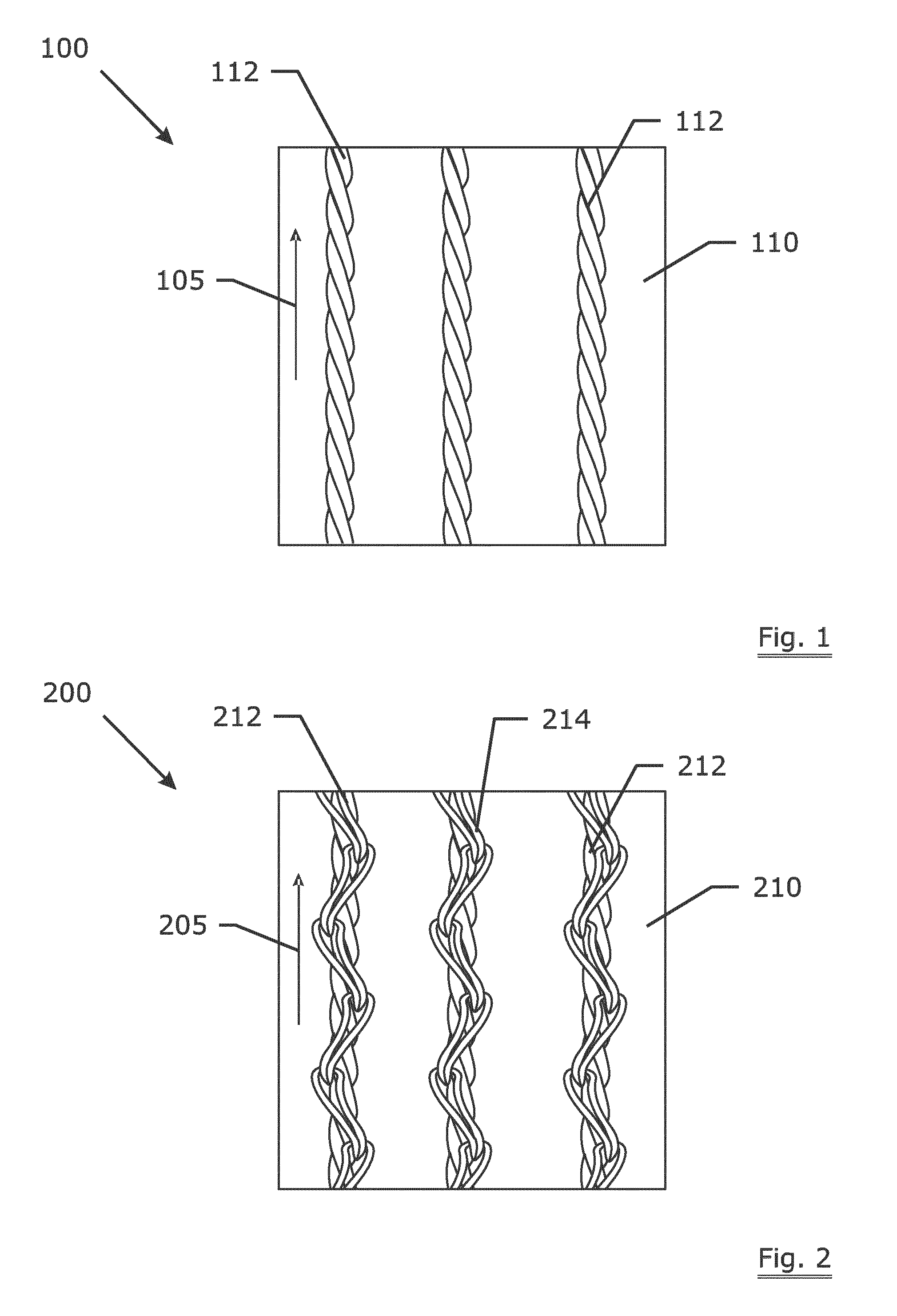
[0114]FIG. 1 is an illustration of a structure 100 for the reinforcement of pavements according to the present invention. The structure 100 comprises a first group of assemblies of grouped metal filaments 112. The assemblies of grouped filaments 112 may comprise steel cords. A preferred steel cord comprises between 2 and 12 filaments, for example a cord having one core filament having a diameter of 0.37 mm and 6 filaments having a diameter of 0.33 mm around this core filament (0.37+6×0.33).

[0115]In alternative embodiments the assemblies of grouped filaments 112 comprise bundles of parallel or substantially parallel filaments, for examples bundles of 12 parallel or substantially parallel filaments. The assemblies of grouped metal filaments 112 of the first group are all oriented parallel or substantially parallel to each other. The orientation of these assemblies of grouped metal filaments of the first group corresponds with the longitudinal direction105 of structure 100. This is mea...

second embodiment

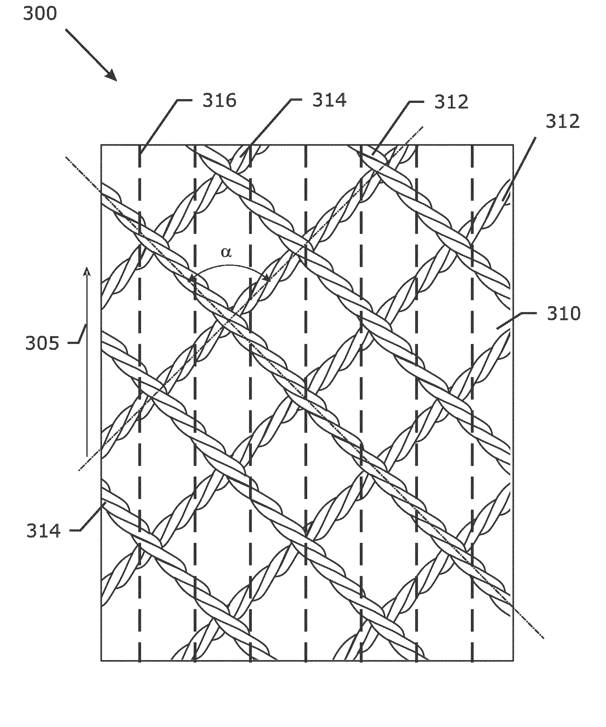
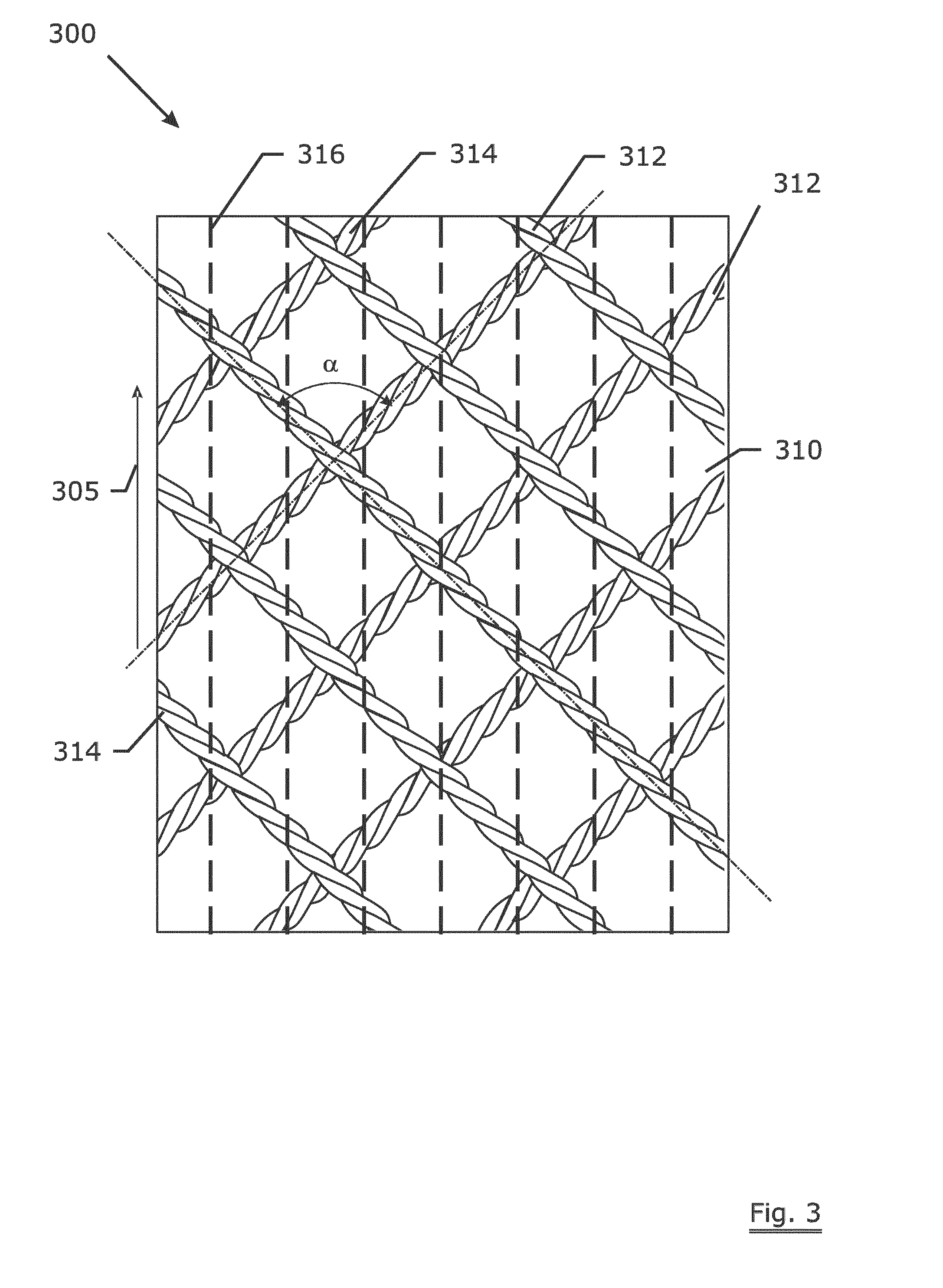
[0119]FIG. 2 is an illustration of a structure 200 for the reinforcement of pavements according to the present invention. The structure 200 comprises a first group of assemblies of grouped metal filaments 212. The assemblies of grouped filaments 212 may comprise steel cords. The assemblies of grouped metal filaments comprise for example steel cords comprising 3 filaments having a diameter of 0.48 mm twisted together (3×0.48 mm).

[0120]In alternative embodiments the assemblies of grouped metal filaments 212 comprise parallel or substantially parallel filaments, for example a bundle of 12 parallel or substantially parallel filaments.

[0121]The assemblies of grouped metal filaments 212 of the first group are all oriented parallel or substantially parallel to each other. The orientation of these assemblies of grouped metal filaments of the first group corresponds with the longitudinal direction 205 of structure 200. This is meaning that the included angle between the orientation of the as...


PUM


Abstract

A structure for the reinforcement of pavements. The structure includes at least a first group of assemblies of grouped metal filaments. These assemblies of grouped metal filaments of said first group are oriented in a first direction in a mutual parallel or mutual substantially parallel position. The assemblies of grouped metal filaments of this first group are coupled to or integrated in a substrate having a non-metal material.

Description

TECHNICAL FIELD[0001]The invention relates to a structure for the reinforcement of pavements. The invention also relates to a reinforced pavement. Furthermore the invention relates to a method of retarding reflective cracking from a distressed and cracked pavement structure.BACKGROUND ART[0002]Repairing roads by applying an overlay, such as an asphalt overlay, to the road surface is well known in the art. A serious drawback of this method includes reflective cracking. Reflective cracking is the process by which an existing crack, discontinuity or joint propagates towards the surface through an overlying layer of asphalt.[0003]Once a reflective crack reaches the surface, an open path is created allowing the penetration of water into the lower layers of the pavement. Left untreated, this situation will lead to further deterioration of the pavement structure and to a reduction in overall serviceability.[0004]The use of interlayers, such as steel wire meshes, geogrids, non-woven structu...

Claims


Application Information

Patent Timeline
Patent Type & Authority Applications(United States)
IPC IPC(8): E01C5/22E01C11/16E01C11/00E01C23/04
CPCE01C11/16E01C11/005E01C23/04E01C5/22D04B21/14D10B2101/20D10B2505/02D10B2505/204E01C11/165E02D29/0225
Inventor CORNELUS, HENKLAMBRECHTS, ANNVERVAECKE, FREDERIK
Owner NV BEKAERT SA
Why Eureka
Try Eureka