
Composite layers for bonding components of a wind turbine rotor blade

a technology of composite layers and rotor blades, which is applied in the field of composite layers for bonding blade components of wind turbines, can solve the problems of blade “rattling”, reducing bond strength, and unnecessary weight of blades, and achieves the effect of convenient unrolling and application

Active Publication Date: 2020-01-14
LM WIND POWER US TECH APS
View PDF21 Cites 1 Cited by
  • Summary
  • Abstract
  • Description
  • Claims
  • Application Information

AI Technical Summary

Benefits of technology

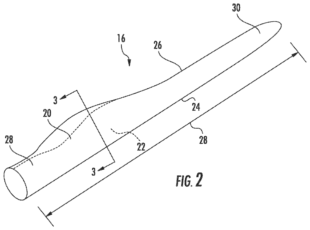
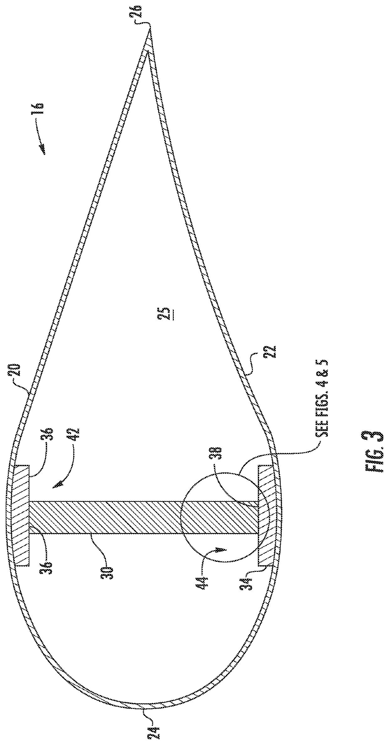
[0011]In one embodiment, as mentioned, the step of placing one or more layers of the wetted composite material at the first and second interfaces may include drawing a fiber material through a bath of resin material, placing the wetted fiber material at the interface, and curing the fiber material at the first and second interfaces. In another embodiment, the step of placing the wetted fiber material at the interface may include unrolling (e.g. manually or automatically) the wetted fiber material at the interface. Thus, in certain embodiments, the wetted fiber material may include a roll of continuous fiber material that can be easily unrolled and applied at the interface. It should also be understood that the method may include any of the additional features and / or steps as described herein.

Problems solved by technology

The excess paste contributes unnecessary weight to the blade and can break off, thereby resulting in blade “rattling” during operation of the wind turbine (a common complaint from wind turbine owners and / or operators).
Also, air voids and unpredictable squeeze-out of the bond paste in the typical configurations can result in areas of decreased bond strength, which is particularly problematic in sections of the blade where repair is not possible from within the rotor blade.
In addition, conventional bond paste can be expensive.

Method used


Image

  • Composite layers for bonding components of a wind turbine rotor blade
  • Composite layers for bonding components of a wind turbine rotor blade
  • Composite layers for bonding components of a wind turbine rotor blade

Examples


Embodiment Construction

[0026]Reference now will be made in detail to embodiments of the invention, one or more examples of which are illustrated in the drawings. Each example is provided by way of explanation of the invention, not limitation of the invention. In fact, it will be apparent to those skilled in the art that various modifications and variations can be made in the present invention without departing from the scope or spirit of the invention. For instance, features illustrated or described as part of one embodiment can be used with another embodiment to yield a still further embodiment. Thus, it is intended that the present invention include such modifications and variations as come within the scope of the appended claims and their equivalents.

[0027]Generally, the present disclosure is directed a method for bonding composite blade components of a rotor blade of a wind turbine. For example, the method includes arranging two or more composite blade components together at an interface. Another step...


PUM

PropertyMeasurementUnit
pressureaaaaaaaaaa
wind energyaaaaaaaaaa
electrical energyaaaaaaaaaa

Abstract

The present disclosure is directed to a method for bonding composite blade components of a rotor blade of a wind turbine. The method includes providing a first blade component being constructed of a first composite material. The method also includes providing a second blade component being constructed of a second composite material. Further, the method includes arranging the first and second blade components together at an interface. Another step includes placing one or more layers of a wetted composite material between the first and second blade components at the interface. The method also includes allowing the one or more layers of the wetted composite material at the interface to cure.

Description

FIELD OF THE INVENTION[0001]The present invention relates generally to the field of wind turbines, and more particularly to composite layers for bonding blade components of a rotor blade of a wind turbine that replace conventional adhesives.BACKGROUND OF THE INVENTION[0002]Wind power is considered one of the cleanest, most environmentally friendly energy sources presently available, and wind turbines have gained increased attention in this regard. A modern wind turbine typically includes a tower, a generator, a gearbox, a nacelle, and one or more rotor blades. The rotor blades are the primary elements for converting wind energy into electrical energy. The blades have the cross-sectional profile of an airfoil such that, during operation, air flows over the blade producing a pressure difference between the sides. Consequently, a lift force, which is directed from a pressure side towards a suction side, acts on the blade. The lift force generates torque on the main rotor shaft, which i...

Claims


Application Information

Patent Timeline
Patent Type & Authority Patents(United States)
IPC IPC(8): F03D1/06B29C65/00B29C65/48B29L31/08
CPCB29C66/721B29C65/488F03D1/0675B29L2031/085B29C65/4815B29C65/4835B29C65/5014B29C65/5021B29C65/5028B29C65/5035B29C65/5057B29C66/112B29C66/1122B29C66/131B29C66/532B29C66/54B29C65/02Y02E10/72Y02P70/50
Inventor YARBROUGH, AARON A.CARUSO, CHRISTOPHER DANIEL
Owner LM WIND POWER US TECH APS
Learn More