Vehicle-body front structure of vehicle

a front structure and vehicle technology, applied in the direction of bumpers, roofs, tractors, etc., can solve the problems of insufficient inability to properly adjust the design flexibility of the vehicle-body front portion, and inability to reduce the amount of impact absorption by deformation of the front side frame. , to achieve the effect of limiting repair costs and appropriate design flexibility

Active Publication Date: 2015-05-12
MAZDA MOTOR CORP
View PDF6 Cites 27 Cited by
  • Summary
  • Abstract
  • Description
  • Claims
  • Application Information

AI Technical Summary

Benefits of technology

[0011]Accordingly, an object of the present invention is to provide a vehicle-body front structure of a vehicle, in which a bumper beam and a front side frame are connected via a crash can, which can properly reduce the impact transmitted to the vehicle-compartment side in the small overlap collision, restraining repair costs of the crash can broken in the low-speed collision as well as maintaining appropriate design flexibility of the vehicle-body front portion.

Problems solved by technology

In this case, there occurs a problem in that a transmission efficiency of a load transmitted to the front side frame may deteriorate.
Further, even in a case in which the object of the small overlap collision is a non-pole member, such as another vehicle traveling in the opposite direction, the transmission efficiency of the load transmitted to the front side frame may improperly deteriorate, compared with a case in which the object and the vehicle body collide with each other in a wide overlap-width in the vehicle width direction.
Therefore, there is a problem in that, in the case of the small overlap collision, the amount of impact absorption by deformation of the front side frame becomes so small that the impact load may be transmitted to a vehicle-compartment side improperly easily.
Therefore, the repair costs may increase more.
Consequently, the repair costs may increase further.
Consequently, there is another problem in that the design of the vehicle-body front portion may be restricted.

Method used


Image

  • Vehicle-body front structure of vehicle
  • Vehicle-body front structure of vehicle
  • Vehicle-body front structure of vehicle

Examples


Embodiment Construction

[0034]Hereafter, preferred embodiments of the present invention will be descried referring to the accompanying drawings. In the following descriptions, the terms regarding directions, such as “front”, “rear”, “longitudinal”, “left”, “right”, or “lateral”, mean respective directions in a state where a vehicle's traveling direction is set as a “front” direction, except particular cases with notes.

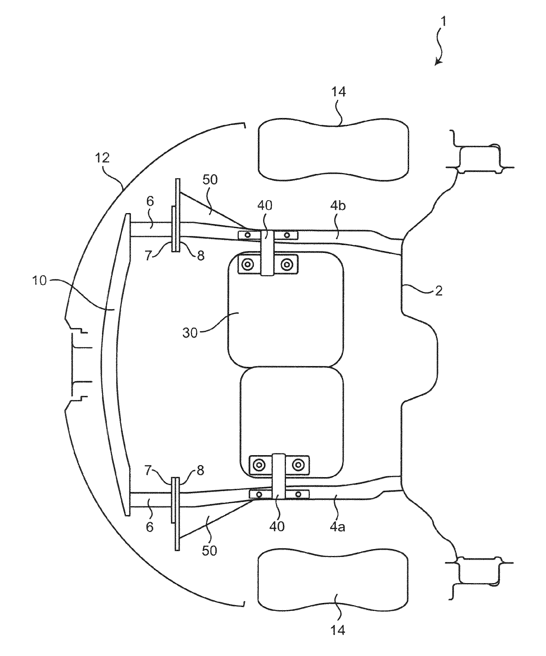
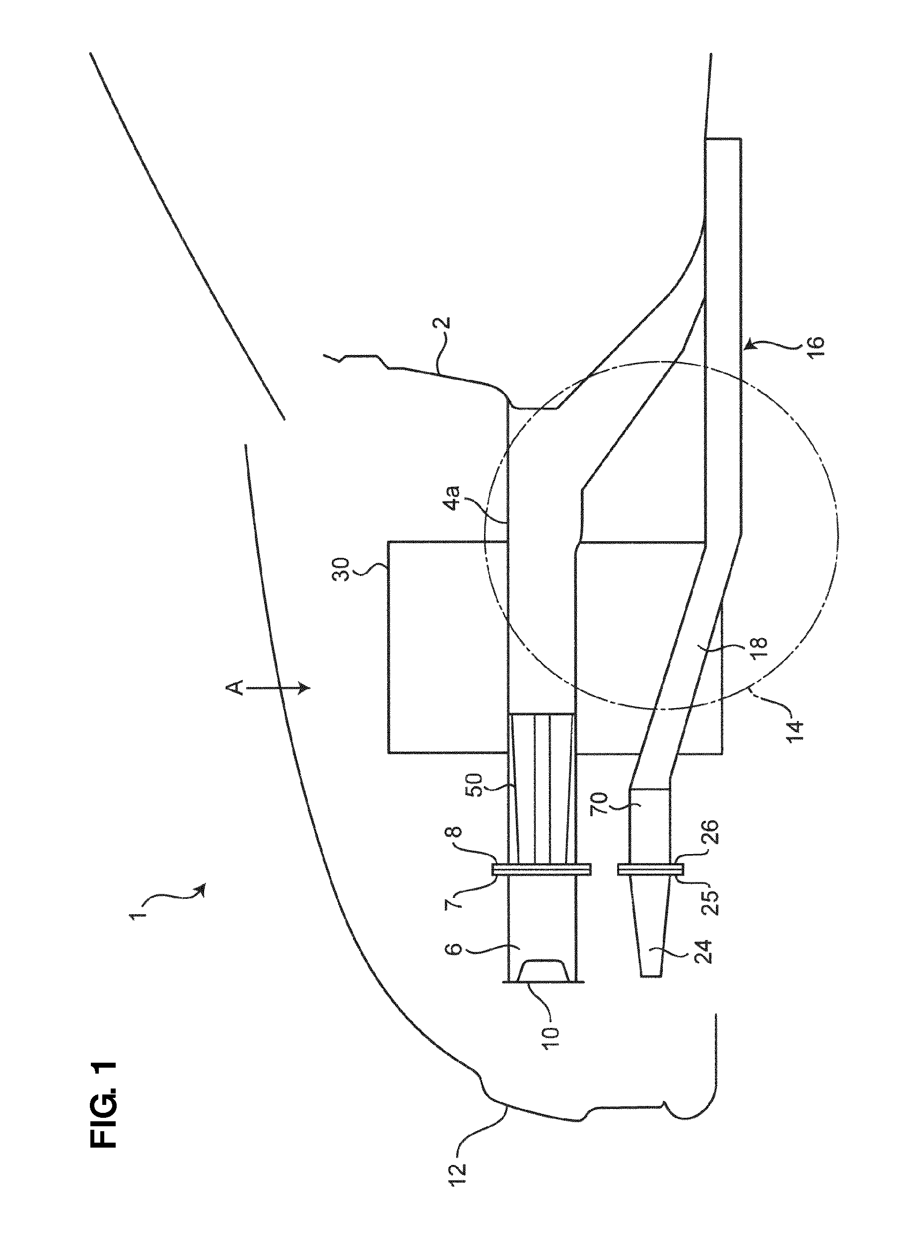
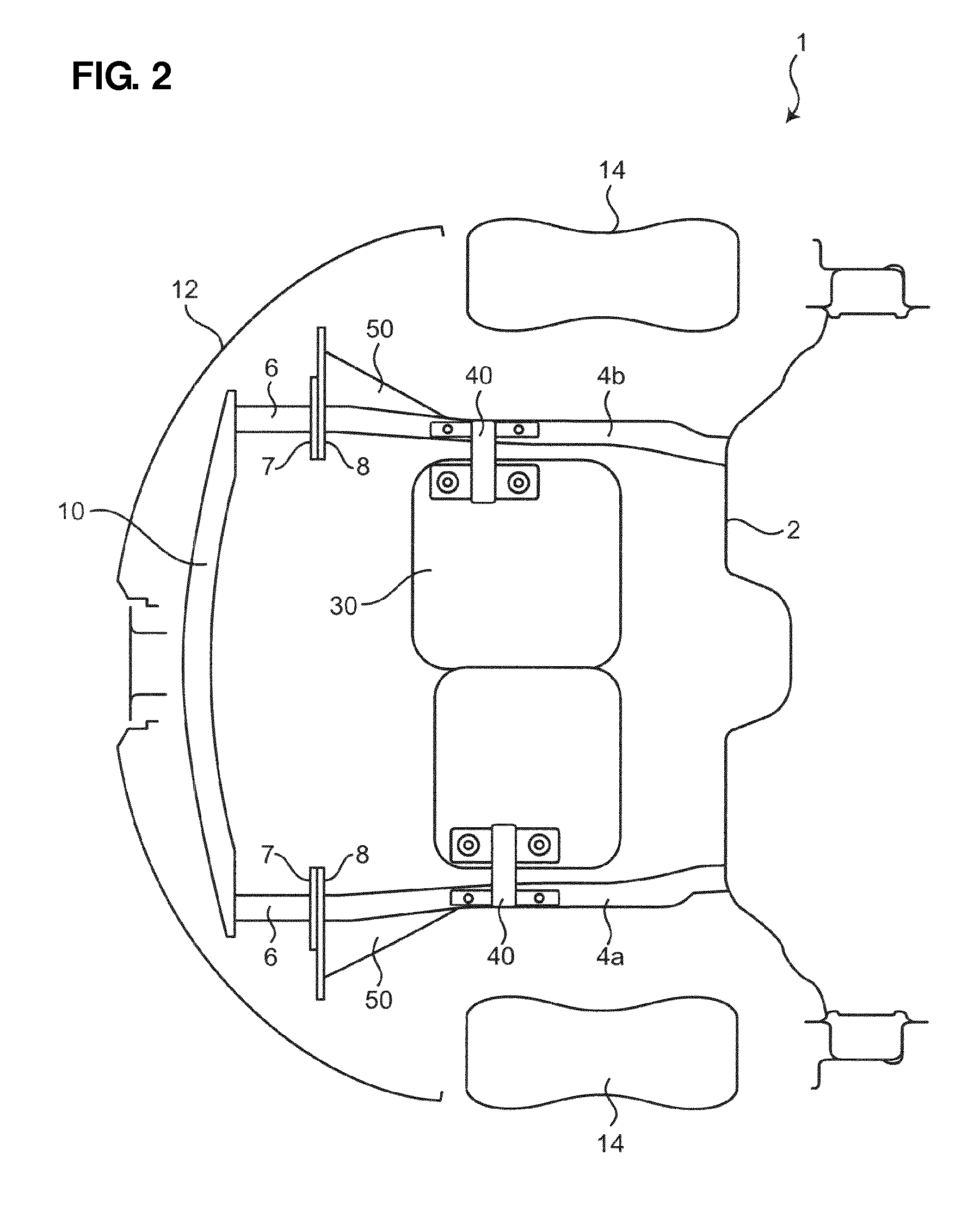
[0035]FIG. 1 is a side view schematically showing a vehicle-body front structure of a vehicle according to an embodiment of the present invention, and FIG. 2 is a schematic plan view of the vehicle-body front structure.

[0036]As shown in FIGS. 1 and 2, a pair of right-and-left front side frames 4 (4a, 4b) is provided to extend in a vehicle longitudinal direction in front of a dash panel 2 of a vehicle 1. Further, a bumper beam 10 is provided to extend in a vehicle width direction at a vehicle-body front portion of the vehicle 1.

[0037]Front end portions of the front side frames 4 are connected ...


PUM


Abstract

A first projection portion projecting outward, in a vehicle width direction, from a front side frame is provided. A front end of the first projection portion is located at the same position, in the vehicle longitudinal direction, as a connection portion of a crash can to the front side frame or located in back of the connection portion. An outward side face of the first projection portion is configured to slant rearward and inward in a plan view. The first projection portion and a power unit are arranged to overlap each other in the vehicle longitudinal direction. Accordingly, an impact transmitted to a vehicle-compartment side in a small overlap collision can be reduced, restraining repair costs of the crash can broken in a low-speed collision as well as maintaining appropriate design flexibility of a vehicle-body front portion.

Description

BACKGROUND OF THE INVENTION[0001]The present invention relates to a vehicle-body front structure of a vehicle, in which a crash can is provided between a bumper beam and a front side frame.[0002]Conventionally, a technology is known, in which a pair of right-and-left front side frames extending in a vehicle longitudinal direction is provided at a vehicle-body front portion so that an impact load is absorbed by the front side frames crushing in a front-end collision of a vehicle.[0003]Herein, the front-end collision of the vehicle occurs at a vehicle-body portion which is located on an outward side, in a vehicle width direction, from the front side frame in some cases. This kind of front-end collision in which the vehicle body collides with an object with a small overlap-width in the vehicle width direction (e.g., about 25% of the vehicle width) is sometimes called “a small overlap collision.”[0004]In a case in which the object of the small overlap collision is a pole member, such as...

Claims


Application Information

Patent Timeline
Patent Type & Authority Patents(United States)
IPC IPC(8): B62D21/15B60R19/34
CPCB62D21/155B60R19/24B60R2019/247
Inventor NAKAMURA, SATOSHITAKESHITA, HIROAKIKOBASHI, MASANOBU
Owner MAZDA MOTOR CORP
Why Eureka
Try Eureka