Fluid coupling

a technology of flue gas and coupling, which is applied in the direction of couplings, water supply installation, transportation and packaging, etc., can solve the problems of increasing the number of parts, the inability to avoid the generation of remaining liquid, and the assembling of the coupling takes a lot of time, so as to reduce manufacturing costs and ensure the reliability and certain seal

Active Publication Date: 2015-05-19
NAGAHORI IND
View PDF29 Cites 35 Cited by
  • Summary
  • Abstract
  • Description
  • Claims
  • Application Information

AI Technical Summary

Benefits of technology

[0036]According to the present invention, by using one member of the guide, the flow paths in the socket are closed, and the socket and the plug main body are sealed with each other, so that the positional relationship of the seal can be ensured, and a reliable and certain seal can be established. Furthermore, the manufacturing cost can be reduced.

Problems solved by technology

Accordingly, in some cases, the generation of remaining liquid cannot be avoided.
Accordingly, the number of parts increases, and its assembling requires a lot of time.

Method used


Image

  • Fluid coupling
  • Fluid coupling
  • Fluid coupling

Examples


Embodiment Construction

[0047]An embodiment of the present invention is described with reference to the attached drawings hereunder.

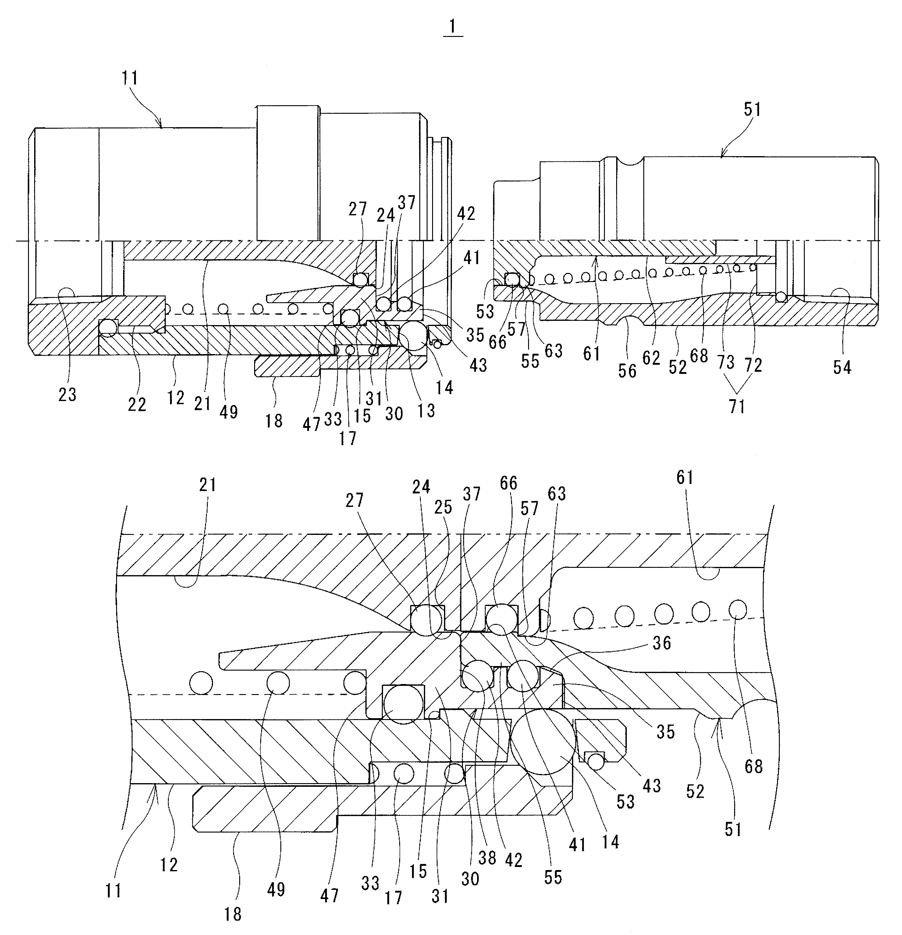
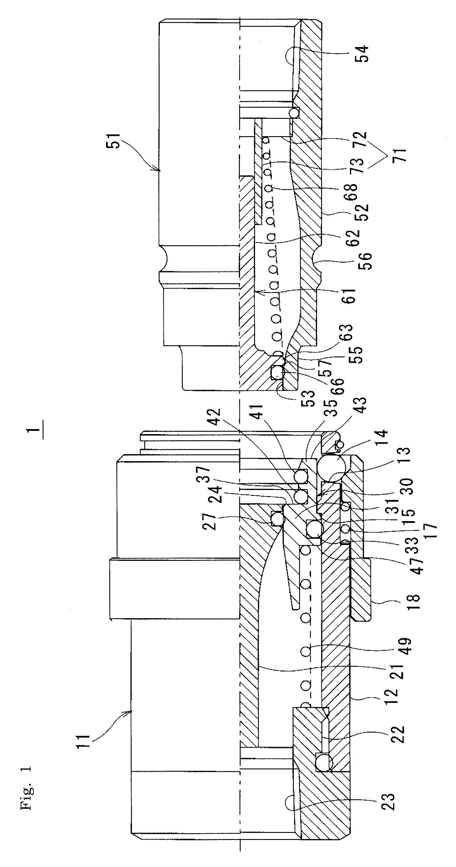
[0048]As illustrated in FIG. 1, a fluid coupling 1 is configured by a socket 11 and a plug 51 which are liquid-tightly connected with each other.

[0049]The socket 11 includes a socket main body 12 having an insertion hole, a fixed valve 21 which is fixed at an inside of the socket main body 12, a guide 30 which is disposed between the fixed valve 21 and the socket main body 12, and a guide spring 49 which biases the guide 30. The guide 30 is engaged with the outer circumference of the fixed valve 21 and the inner circumference of the socket main body 12 so that a flow path formed between the fixed valve 21 and the socket main body 12 is closed.

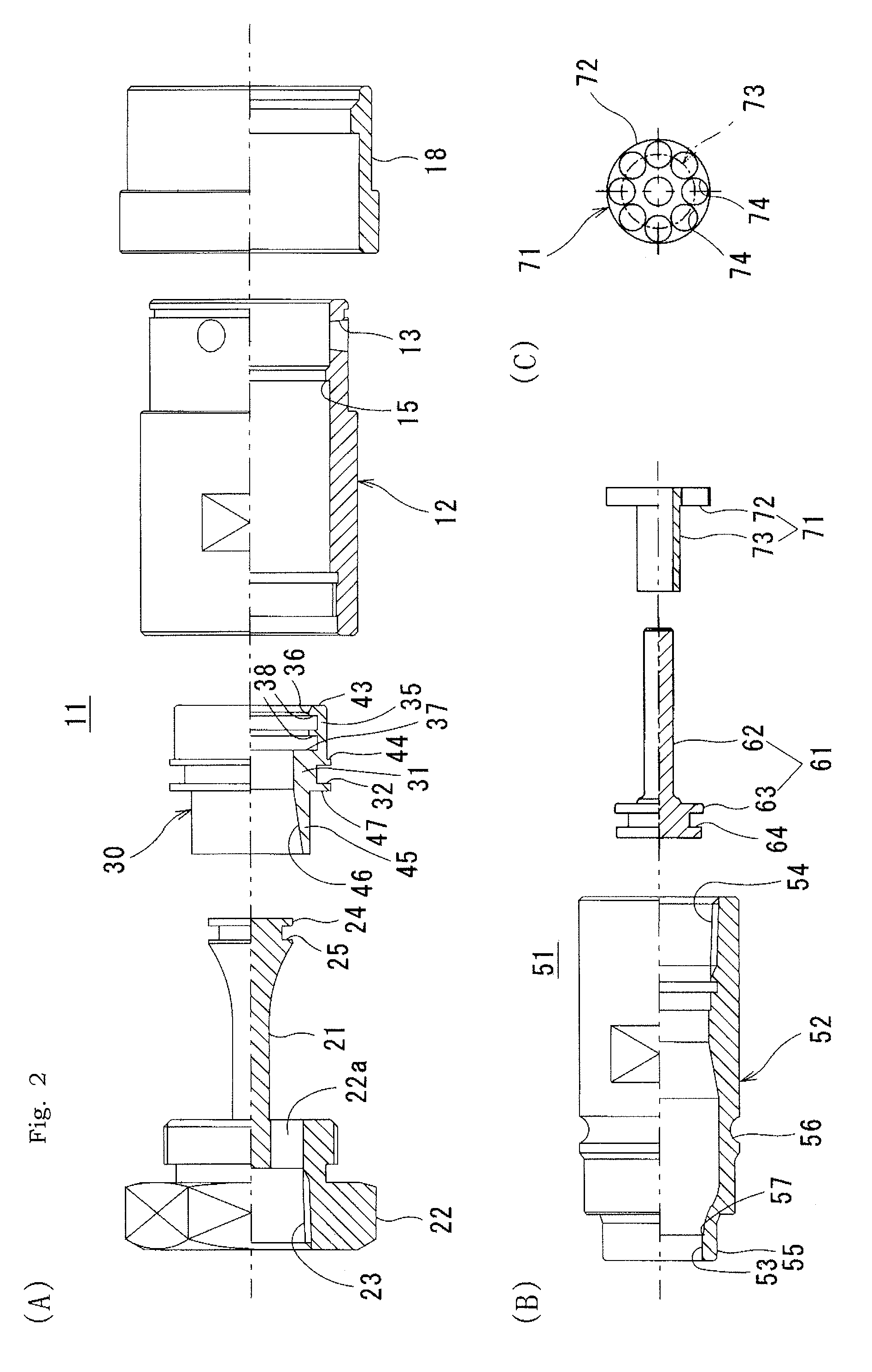
[0050]As illustrated in FIG. 2A, the socket main body 12 has a cylindrical shape. A stopper 15 is disposed on the inner surface of the socket main body 12 so as to protrude therefrom. A plurality of holes 13 for locking the steel balls ar...


PUM


Abstract

A fluid coupling includes a socket with a socket main body, a fixed valve, a guide which is engaged with the fixed valve and biased to be pressed against an inner surface of the socket main body, and a guide spring which biases the guide, and a plug with a plug main body, a movable valve, a valve spring, and a valve holder which supports the movable valve and the valve spring. When the plug is inserted into the socket, the guide moves rearward against a biasing force of the guide spring to connect a flow path between the plug and the socket. A fitted portion, which is fitted into the distal end of the plug, is disposed at the end portion of the guide. First seal members are disposed between the fitted portion and a distal end of the plug.

Description

TECHNICAL FILED[0001]The present invention relates to a fluid coupling which is configured by a plug and a socket.BACKGROUND ART[0002]FIG. 8 illustrates a state of a conventional fluid coupling whose plug 101 and socket 102 are separated from each other, FIGS. 9A and 9B illustrate a state in which the plug 101 and the socket 102 are connected with each other, and FIG. 10 illustrates a state in which the plug 101 is pulled away from the socket 102.[0003]As illustrated in FIG. 8, a socket-side flow path is formed between an inner surface of the socket 102 and a fixed valve 103 which is fixed at an inside of the socket 102. A socket-side seal 105, which is disposed at a seal guide 104, is biased by a guide spring 106 so as to be pressed against the fixed valve 103, and the seal guide 104 is abutted against the inner surface of the socket 102 via a first seal ring 107, so that the socket-side flow path is closed. Steel balls 109, which are housed in holes 108 for locking the steel balls...

Claims


Application Information

Patent Timeline
Patent Type & Authority Patents(United States)
IPC IPC(8): F16L37/32F16L37/28F16L37/34
CPCF16L37/28F16L37/34Y10T137/87941Y10T137/87949Y10T137/9029F16L37/23F16L37/32
Inventor ABURA, YOSHINORIISHIBE, KATSUYAMORIIKI, ATSUSHI
Owner NAGAHORI IND
Why Eureka
Try Eureka