
Double dogleg wide stance brake shoe web

a double dogleg, wide-stance technology, applied in the field of brakes, can solve the problems of many technical problems, and achieve the effect of wide-stance and cost-effectiveness

Active Publication Date: 2015-05-19
BENDIKS SPAJSER FAUNDEJSHN BREJK LLK
View PDF14 Cites 1 Cited by
  • Summary
  • Abstract
  • Description
  • Claims
  • Application Information

AI Technical Summary

Benefits of technology

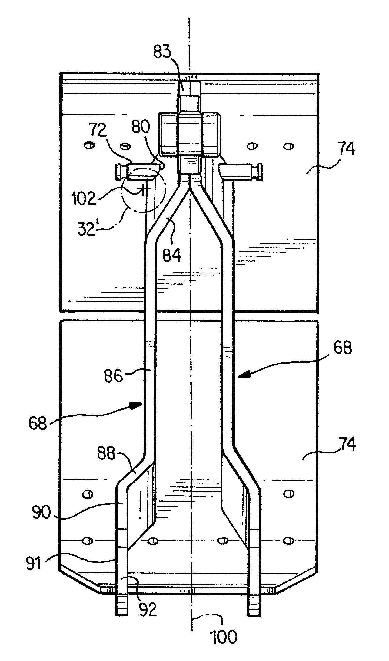
[0019]One significant feature of this design is that the stance of the webs at the anchor pin is wider than the amount that the return spring is away from a return spring centerline. The centerline of the offset spring thus falls in between the two outside edges of the widened webs at the anchor pin. Variations may have straight or tapered webs that stand much wider on anchor pins. Advantages provided by this configuration include minimizing brake shoe rocking and reductions in vibration and noise.
[0030]Again, the present design provides a low cost, low risk design with no extra parts required, is easy to service, and is compatible with most common drum brake designs used today.

Problems solved by technology

Since a drum brake using an off-centerline return spring has unbalanced forces, the brake shoes tend to “rock” or tilt and lift off from one side of the anchor pin.
Tilting of drum brake shoes in this manner causes many technical issues.

Method used


Image

  • Double dogleg wide stance brake shoe web
  • Double dogleg wide stance brake shoe web
  • Double dogleg wide stance brake shoe web

Examples


Embodiment Construction

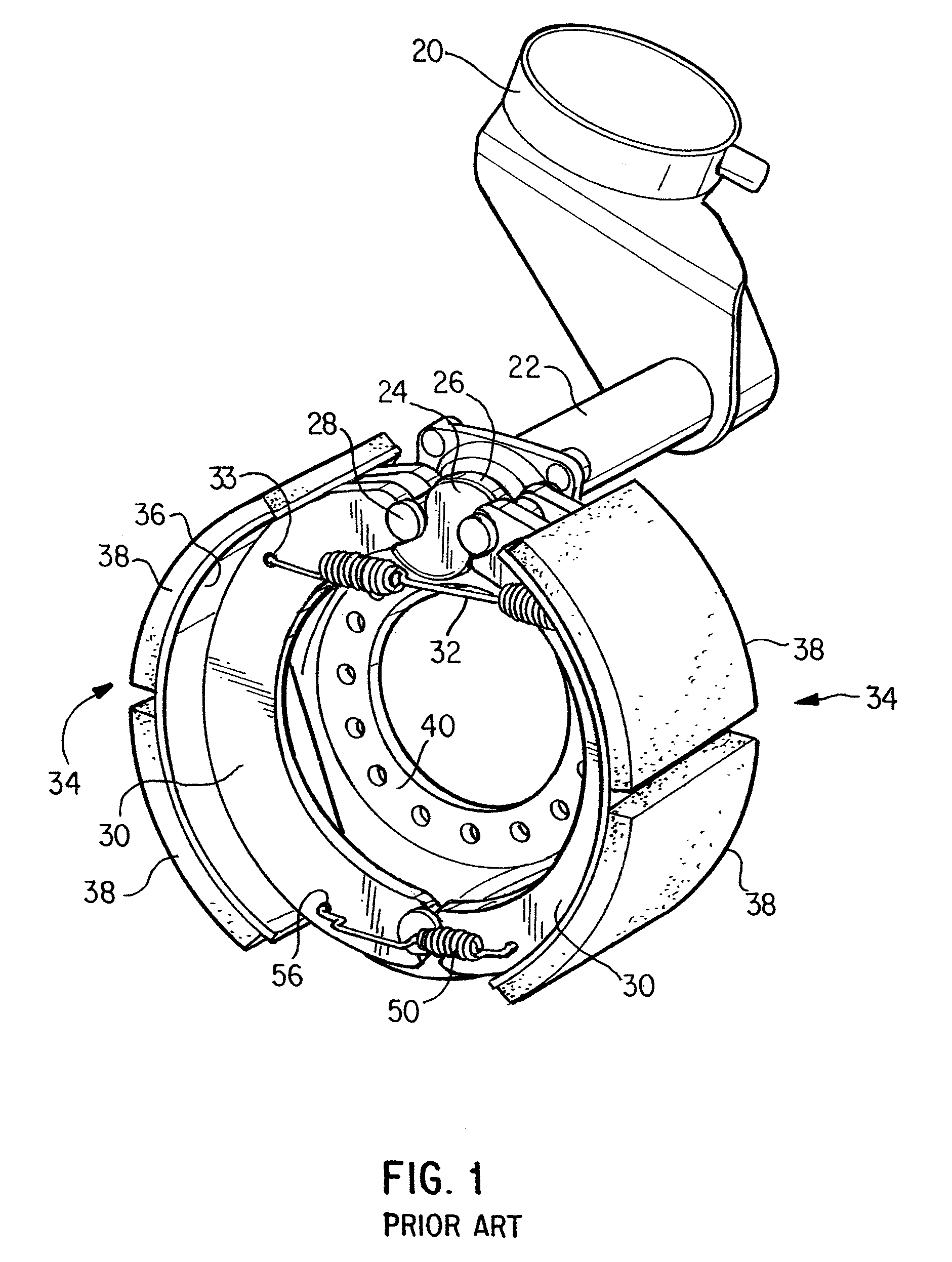
[0037]FIG. 1 shows one conventional drum brake configuration in which drum brake shoe webs according to this invention are useable. The configuration in FIG. 1 includes an air or hydraulic fluid actuator 20 interconnected by a lever arrangement to a rotatable shaft extending through a sleeve 22. The rotatable shaft terminates in a double sided cam 24 having cam surfaces 26. Cam follower bearings 28, which, if preferred, could be configured as rollers, are mounted to actuated ends of a pair of drum brake shoes 34 in a conventional manner. Each bearing 28 is positioned so as to engage a corresponding cam surface 26 under a spring bias applied by a return spring 32. Ends of the return spring 32 are received in holes 33 defined adjacent the actuated ends of the drum brake shoes 34.

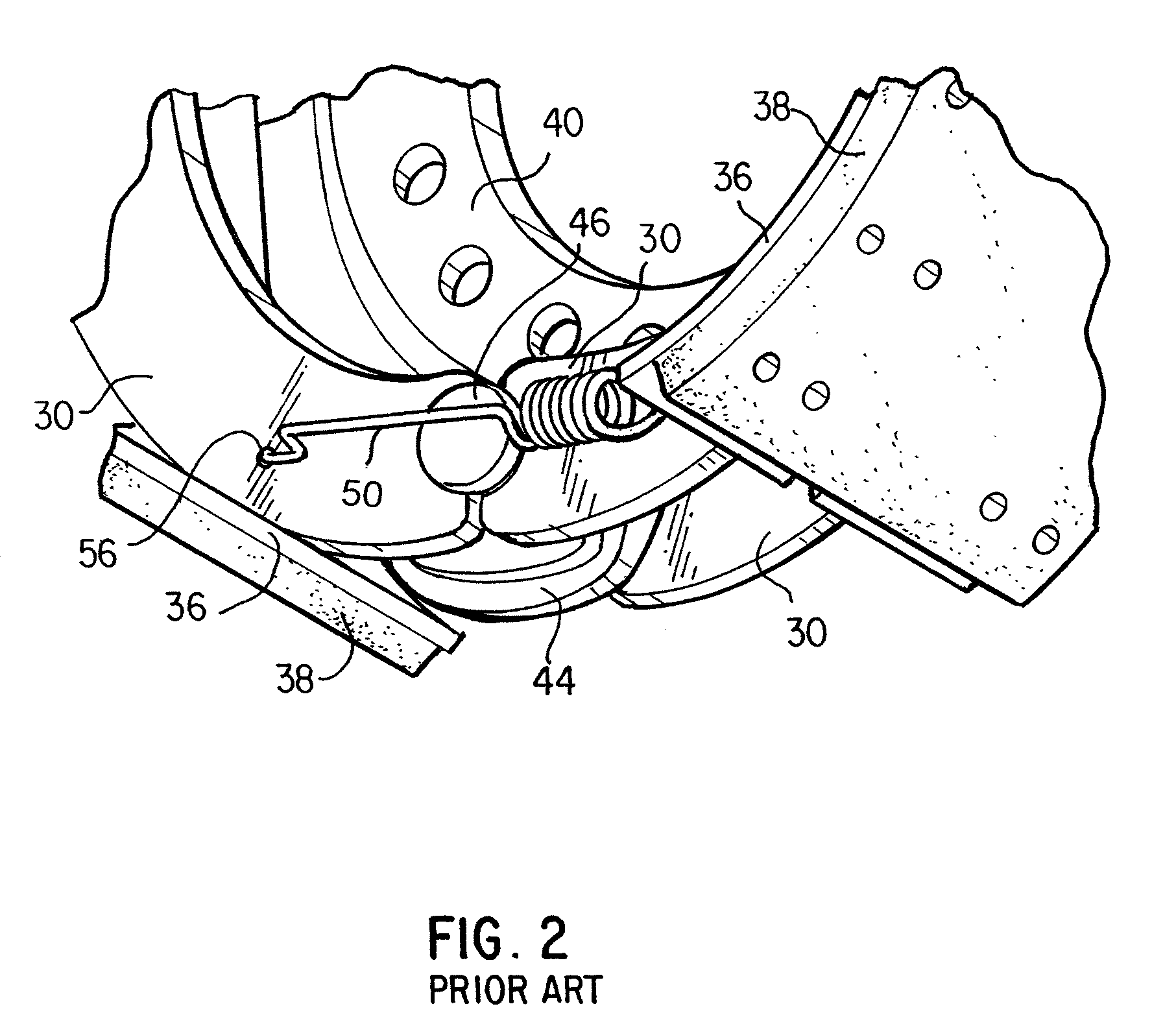
[0038]As shown in FIGS. 1 and 2, each drum brake shoe 34 includes a pair of parallel brake shoe webs 30. A part-circular lining table 36 is formed together with or secured to each pair of parallel webs 30, and...


PUM


Abstract

A drum brake shoe has first and second webs, with the first web including a first end section to be located adjacent a brake shoe actuation element, a second end section to be located adjacent a brake shoe anchor element, and a central section extending between the first and second end sections. Similarly, the second web includes a first end section to be located adjacent the brake shoe actuation element, a second end section to be located adjacent the brake shoe anchor element, and a central section extending between the first and second end sections of the second web. At least one lining table is disposed at circumferentially outer portions of the first and second webs, and a pin or other return spring mounting is provided by at least the first web. The brake shoe is particularly configured so that a brake shoe return spring, which is connectable to the return spring mounting, is positioned so that a center line of the return spring is offset from an axial center line of the lining table but located axially inboard of an outside edge of the second end section of the first web.

Description

BACKGROUND OF THE INVENTION[0001]1. Field of the Invention[0002]This invention concerns “foundation” brakes provided with drum brake shoe webs that are angled, or that “dogleg,” at anchor ends to establish more stable stances on drum brake anchor pins. The invention can be utilized in conjunction with standard drum brakes already in use, but is especially advantageous and cost effective when used in configurations having offset return springs.[0003]2. Description of Related Art[0004]An offset return spring configuration adds side loading to drum brake shoes and forces ends of the shoes to lift off of the anchor pin. Since a drum brake using an off-centerline return spring has unbalanced forces, the brake shoes tend to “rock” or tilt and lift off from one side of the anchor pin. Tilting of drum brake shoes in this manner causes many technical issues.[0005]Brake shoes that somehow capture the anchor pin are currently used to eliminate this rocking or tilting. This is generally done by...

Claims


Application Information

Patent Timeline
Patent Type & Authority Patents(United States)
IPC IPC(8): F16D65/04F16D51/16F16D65/08F16D125/30
CPCF16D65/08F16D2125/30
Inventor FLODIN, TROY ALLENLYON, THOMAS E.
Owner BENDIKS SPAJSER FAUNDEJSHN BREJK LLK
Learn More