Attachment system for hand-held tools

a technology for attaching systems and hand-held tools, which is applied in the field of attachment systems for hand-held tools, can solve the problems of compromising worker safety, tethering each tool becomes a safety hazard in itself, and the job is made more difficult and frustrating for workers, so as to reduce the entanglement of tethers, facilitate the placement of clip protrusions, and reduce the effect of accidental drops of hand-held tools

Inactive Publication Date: 2015-05-26
PURE SAFETY GRP INC
View PDF18 Cites 7 Cited by
  • Summary
  • Abstract
  • Description
  • Claims
  • Application Information

AI Technical Summary

Benefits of technology

[0009]It is an object of the present invention to permit workers to quickly switch between tethered tools.
[0011]It is another object of the present invention to provide an attachment system that reduces and / or prevents accidental drops of hand-held tools.
[0012]It is another object of the present invention to reduce entanglement of tethers used with multiple hand-held tools.
[0014]In one embodiment, the attachment system has a housing with a proximal housing end portion, a distal housing end portion, and a peripheral wall defining an open central region within the housing. The peripheral wall has a first slot and a second slot each with a predefined slot width and extending through the peripheral wall to the open central region. The first slot and the second slot each has a proximal slot end and a distal slot end, where the proximal slot end has a proximal slot end width that is greater than the predefined slot width. The enlarged proximal slot facilitates placing the clip protrusion in the first or second slot when engaging a clip member with the housing.
[0028]The present invention also includes a method of tethering a hand tool. In one embodiment, the method includes tethering a tool to a housing assembly having a housing and a rotating member as described above. The user engages a first clip member with the housing assembly, where the clip member has a clip body, a housing-side surface, and a clip protrusion as described above. The user moves the clip member distally along the first slot with the tip member in engagement with the first sloping surface to cause the rotating member to rotate in a first direction about the central longitudinal axis and cause the catch surface to align with the tip portion. This movement retains the first clip member in engagement with the housing assembly.
[0032]In one embodiment, the peripheral wall is substantially cylindrical. In other embodiments, a biasing member is disposed between the housing and the rotating member. In one embodiment, the biasing member is configured to rotationally bias the rotating member towards an intermediate position between the first position and the second position. In another embodiment, the biasing member is configured to bias the rotating member along the central longitudinal axis to establish frictional engagement between the rotating member and the housing to prevent unrestricted rotation of the rotatable member.

Problems solved by technology

When a worker uses many tools to complete a task, tethering each tool becomes a safety hazard in itself.
When each tool is separately tethered, the worker's job is made more difficult and frustrating when tethers become tangled.
Also, the worker's safety is compromised by having a plurality of tethers in the work area because the likelihood increases that the worker will become tangled in or tripped by tethers.

Method used


Image

  • Attachment system for hand-held tools
  • Attachment system for hand-held tools
  • Attachment system for hand-held tools

Examples


Embodiment Construction

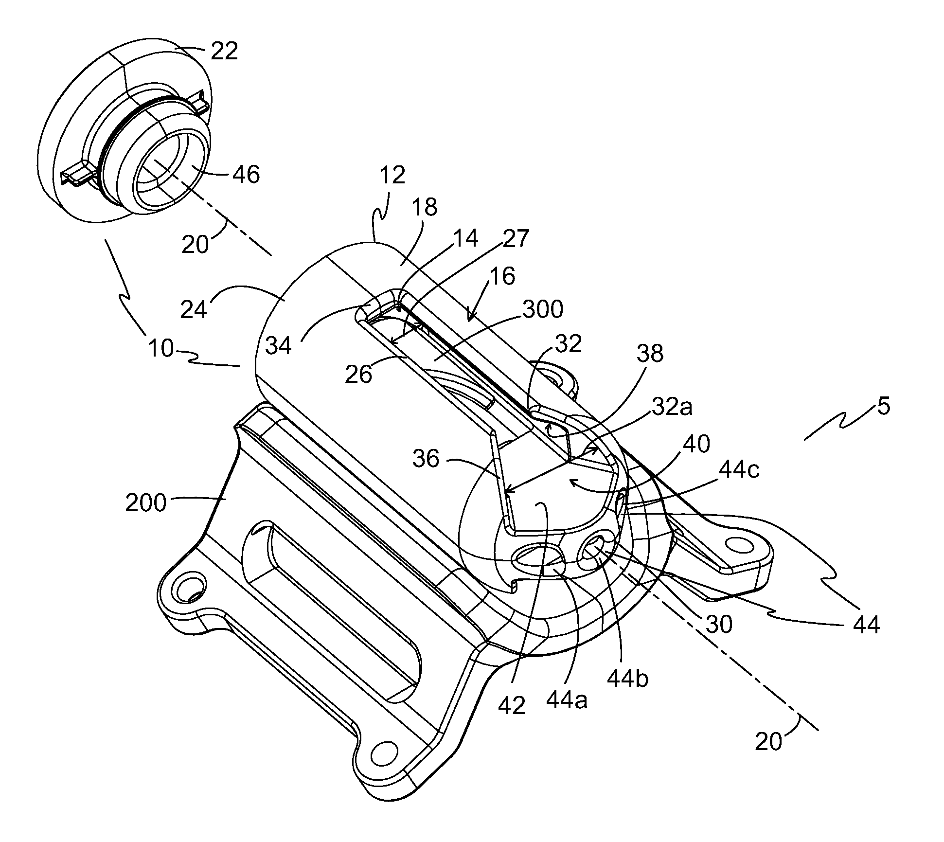
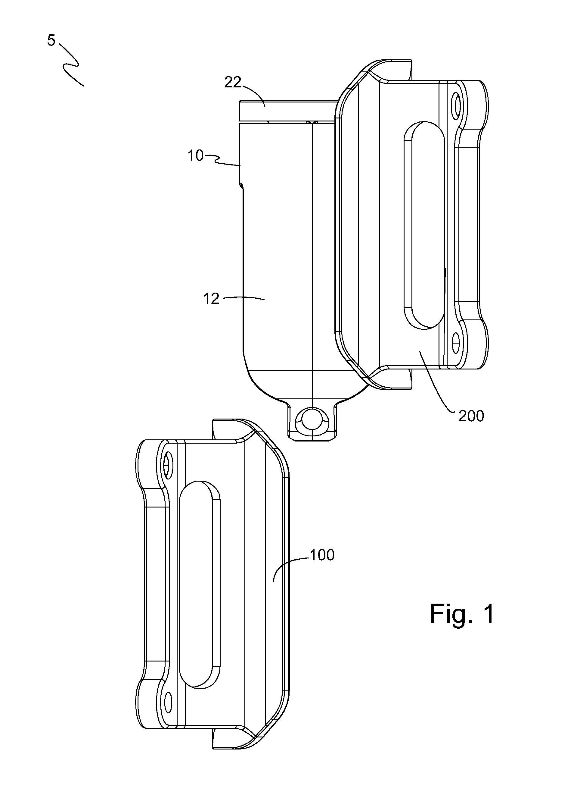
[0051]The preferred embodiments of the present invention are illustrated in FIGS. 1-13. FIG. 1 illustrates one embodiment of an attachment system 5 that includes a housing assembly 10, a first clip member 100 separated from housing assembly 10, and a second clip member 200 engaged with housing assembly 10. Housing assembly 10 includes a housing 12, an optional cap 22, and a rotating member 300 (not visible) disposed in an open central region 14 (not visible) within housing 12 as is discussed below in more detail with reference to FIGS. 3-5.

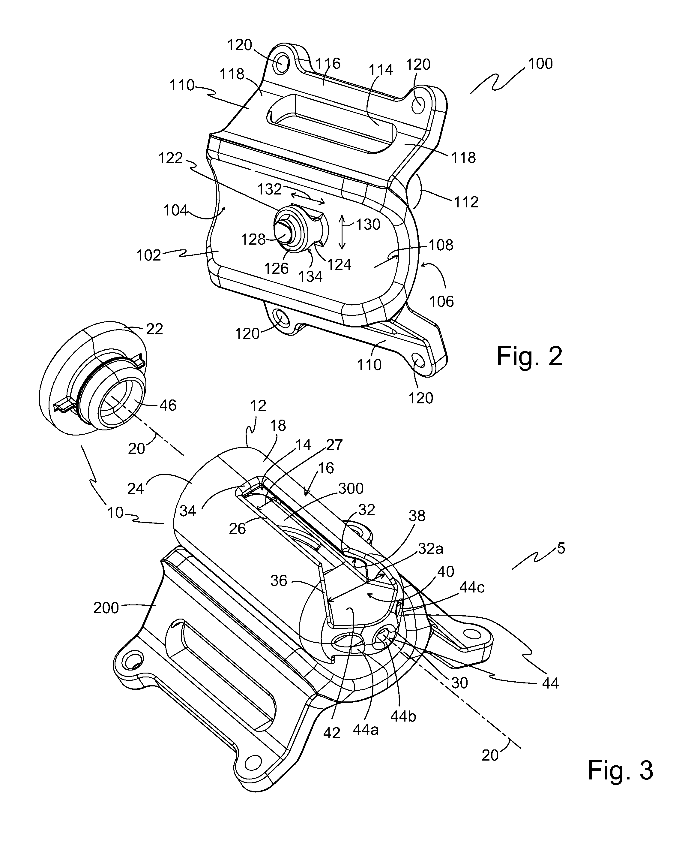
[0052]FIG. 2 illustrates a perspective view of first clip member 100 as shown in FIG. 1. First clip member 100 and second clip member 200 are preferably identical and interchangeable, so the features described here for first clip member 100 also apply to embodiments of second clip member 200. First clip member 100 has a clip body 102 with a housing-side surface 104 and an outside surface 106. In one embodiment, housing-side surface 104 is shaped t...


PUM

PropertyMeasurementUnit
internal angleaaaaaaaaaa
angleaaaaaaaaaa
angleaaaaaaaaaa

Abstract

An attachment system for tools includes a housing with a wall defining an open central region. The housing has a first slot and a second slot spaced from the first slot, each slot extending through the wall to the open central region. A rotating member is disposed in the open central region. A clip member has a clip protrusion with neck, head and tip portions, the neck portion sized to be slidably received in one of the slots. The tip portion is configured to engage the rotating member to cause it to rotate about a central longitudinal axis as the neck portion moves distally along one of the slots, causing a catch surface to align with the tip portion and a channel to align with a tip portion of a second clip member retained in the second slot, thereby retaining the first clip member and releasing the second clip member.

Description

BACKGROUND OF THE INVENTION[0001]1. Field of the Invention[0002]The present invention relates generally to tool accessories and more particularly to an attachment system for hand-held tools.[0003]2. Description of the Prior Art[0004]Lanyards, tethers, hooks, and similar restraints are used to prevent accidental dropping of tools. These restraints are particularly useful in environments where a tool drop can cause substantial damage or harm to plant equipment, workers, or objects below a worker who accidentally drops a tool.[0005]One method of restraining tools is to clip one end of a tether to an opening in the handle of a tool (e.g., an adjustable wrench) and to clip the other end of the tether to the worker's belt or to a nearby structure. When workers properly tether a tool in this way, accidental drops can be eliminated or greatly reduced. However, if a worker uses many tools to complete a task, then the worker implementing this method must tether each tool. The worker may switc...

Claims


Application Information

Patent Timeline
Patent Type & Authority Patents(United States)
IPC IPC(8): A45F5/00
CPCA45F5/00A45F5/021A45F2005/008A45F2200/0575Y10T24/1394Y10T29/49826Y10T29/49947
Inventor MOREAU, DARRELL A.MOREAU, ANDRE W.BACHMAN, BEN
Owner PURE SAFETY GRP INC
Why Eureka
Try Eureka