Racetrack memory with electric-field assisted domain wall injection for low-power write operation

a domain wall and write operation technology, applied in the field of computer memory technology, can solve problems such as large power dissipation

Active Publication Date: 2015-05-26
INT BUSINESS MASCH CORP
View PDF9 Cites 11 Cited by
  • Summary
  • Abstract
  • Description
  • Claims
  • Application Information

AI Technical Summary

Problems solved by technology

Both of these methods typically require large current densities and therefore are prone to large power dissipations.

Method used


Image

  • Racetrack memory with electric-field assisted domain wall injection for low-power write operation
  • Racetrack memory with electric-field assisted domain wall injection for low-power write operation
  • Racetrack memory with electric-field assisted domain wall injection for low-power write operation

Examples


Embodiment Construction

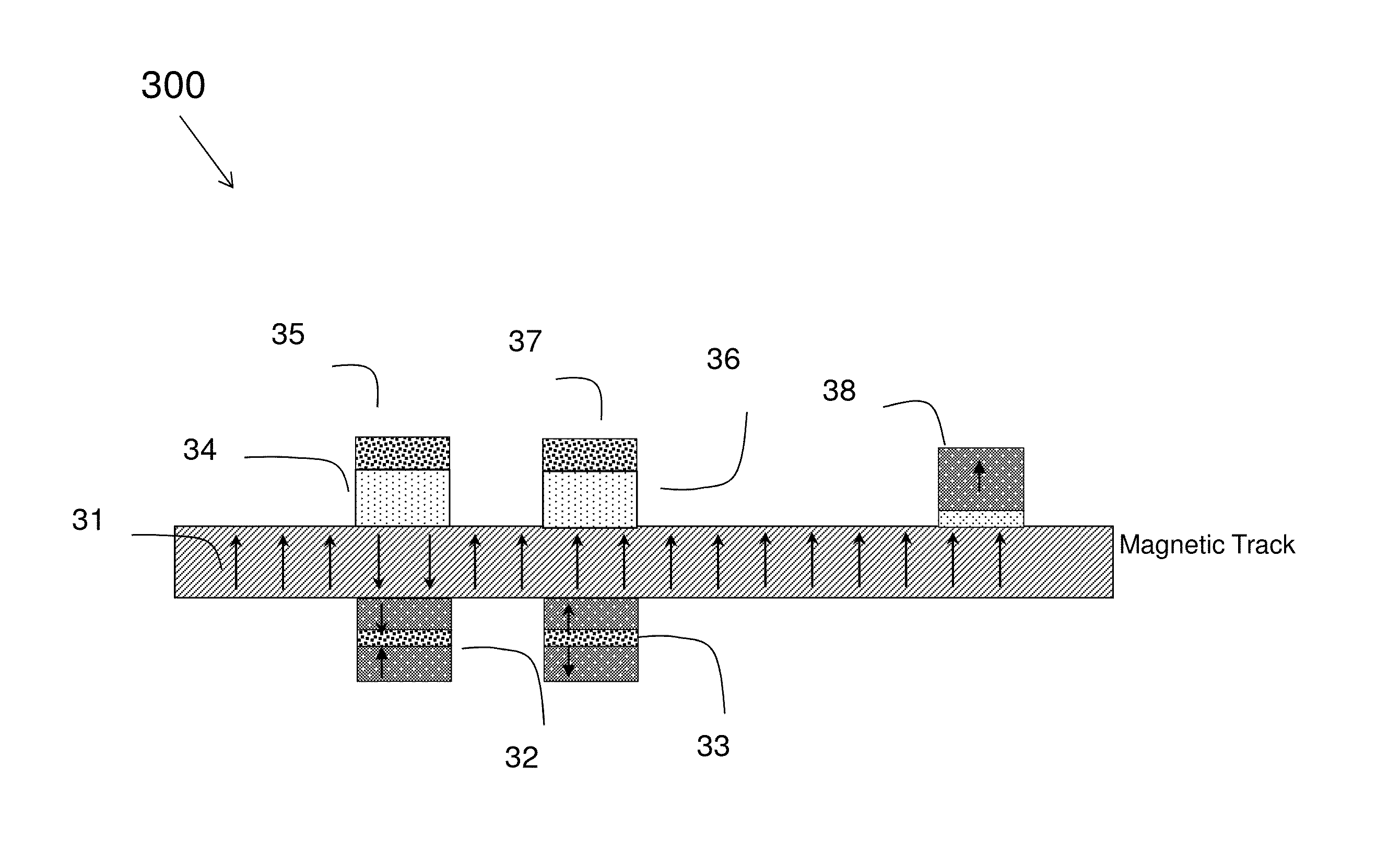
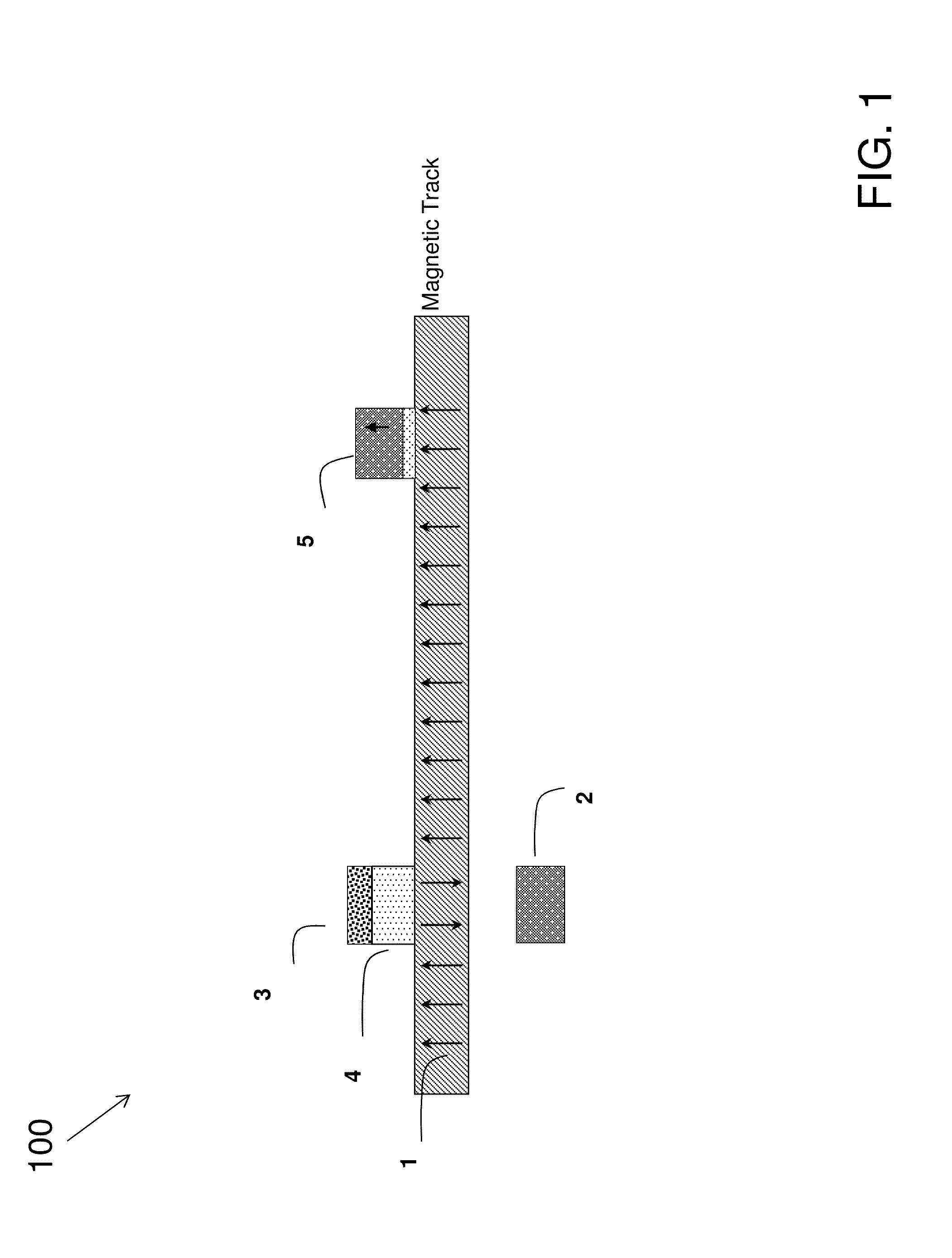
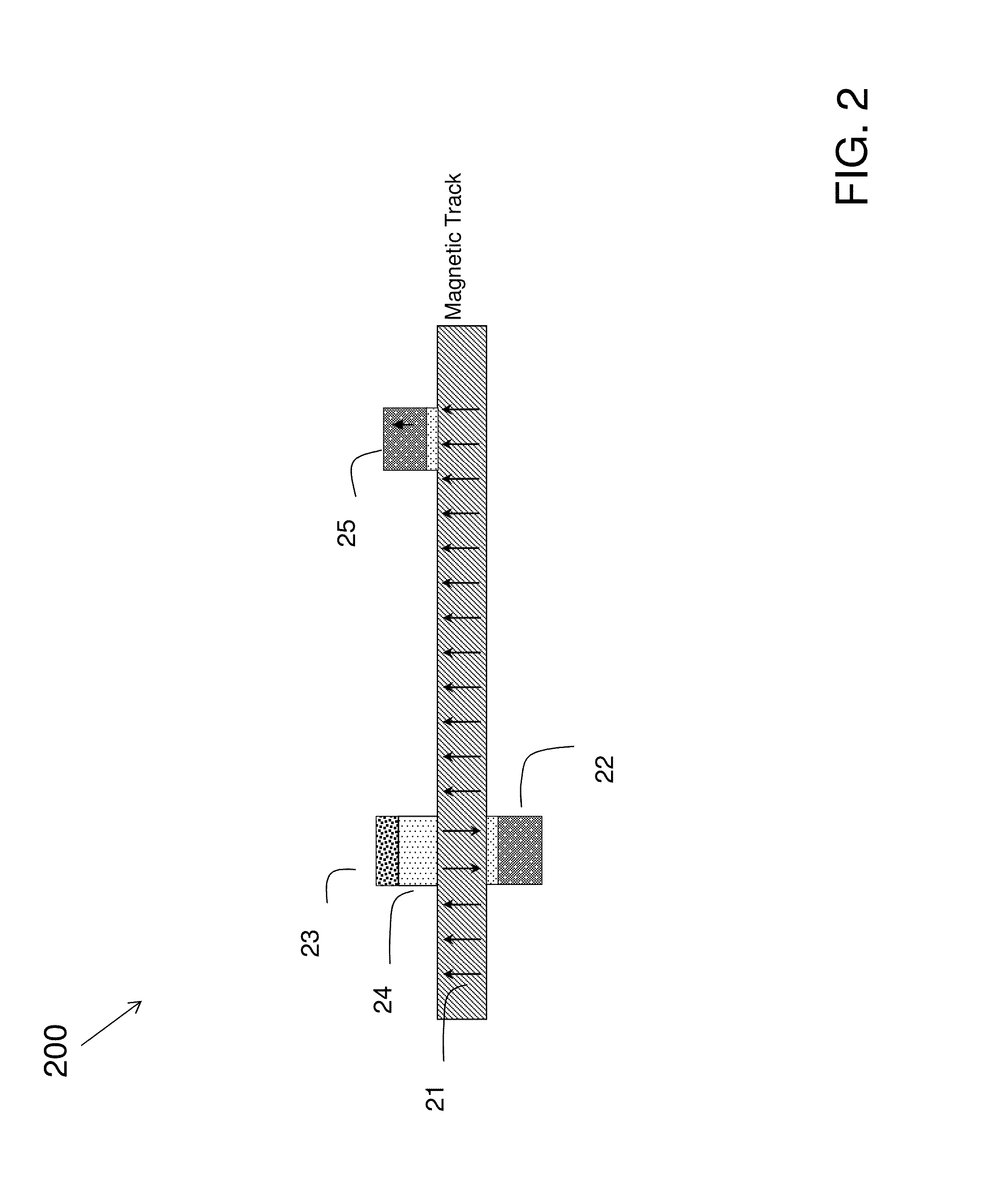
[0012]It is noted that various connections are set forth between elements in the following description and in the drawings (the contents of which are included herein by way of reference). It is noted that these connections in general and, unless specified otherwise, may be direct or indirect and that this specification is not intended to be limiting in this respect. In this regard, a coupling of entities may refer to either a direct or an indirect connection.

[0013]Methods, apparatuses, and systems are described for injecting domain walls in a magnetic racetrack memory. The memory may comprise a magnetic domain wall shift register. The injection of the domain wall may be based on an electrical control of surface anisotropy at one or more ferromagnetic metal / dielectric interfaces. Power dissipation may be minimized using one or more techniques described herein. In some embodiments, local anisotropy in a nanowire may be modulated via an electric field. Use of the electric field for wri...


PUM


Abstract

Embodiments are directed to injecting domain walls in a magnetic racetrack memory. In some embodiments, a racetrack comprising a nanowire is coupled with a gate in order to manipulate an anisotropy associated with the nanowire. The racetrack and gate is coupled with a pinning layer configured to establish a magnetization direction in the nanowire.

Description

FIELD OF INVENTION[0001]The present invention relates generally to computer memory technology, and more specifically, to an injection of a domain wall in a magnetic shift register memory.DESCRIPTION OF RELATED ART[0002]Magnetic shift register memories may make use of magnetic domains for purposes of storing data. Magnetic shift register memories require the injection of a domain wall along the length of a wire (e.g., a racetrack wire). Domain walls can be injected in a magnetic stripe via a local magnetic field at a location along the racetrack wire, or via current-induced spin-torque switching with a current injected from a reference layer via a metallic or insulating spacer at various locations along the wire. Both of these methods typically require large current densities and therefore are prone to large power dissipations.BRIEF SUMMARY[0003]Embodiments are directed to a method for injecting domain walls in a magnetic racetrack memory comprising: coupling a racetrack comprising a...

Claims


Application Information

Patent Timeline
Patent Type & Authority Patents(United States)
IPC IPC(8): G11C19/02G11C19/08
CPCG11C19/0808G11C19/02G11C19/0816G11C19/0841G11C11/161
Inventor ANNUNZIATA, ANTHONY J.GAJEK, MARCIN J.
Owner INT BUSINESS MASCH CORP
Why Eureka
Try Eureka