
Hole adapter insert for lock mounting

Active Publication Date: 2015-06-09
AYREST ROBERT B
View PDF18 Cites 1 Cited by
  • Summary
  • Abstract
  • Description
  • Claims
  • Application Information

AI Technical Summary

Benefits of technology

The patent is about a lock assembly that is used to secure a panel to a wall or machine. The lock is held in place by an adapter, which aligns the lock and prevents it from spinning. This reduces the amount of torque that needs to be applied, which prevents damage to the panel and ensures the lock is secure. The lock is held in place not by tightening it, but by keeping it stable in the adapter. This makes it easier to install and reduces the risk of damage to the panel.

Problems solved by technology

However, in lower volume numbers it is necessary to cut with a laser beam, water jet, or punch tool to form the D / DD opening, which can add expense to production costs.
Punch cannot be used for plastic panel without fracturing the material.
It is necessary to severely tighten the lock nut to effect a secure installation, but too much compression from the lock nut may damage the plastic panel.
Furthermore, lock bodies, which are often fabricated of brass or steel, are much harder that the plastic panel material, and over time the panel will wear against the harder material and the lock will loosen in its mount and begin to yield in angular turning movement when the key is rotated in the lock body.

Method used


Image

  • Hole adapter insert for lock mounting
  • Hole adapter insert for lock mounting
  • Hole adapter insert for lock mounting

Examples


Embodiment Construction

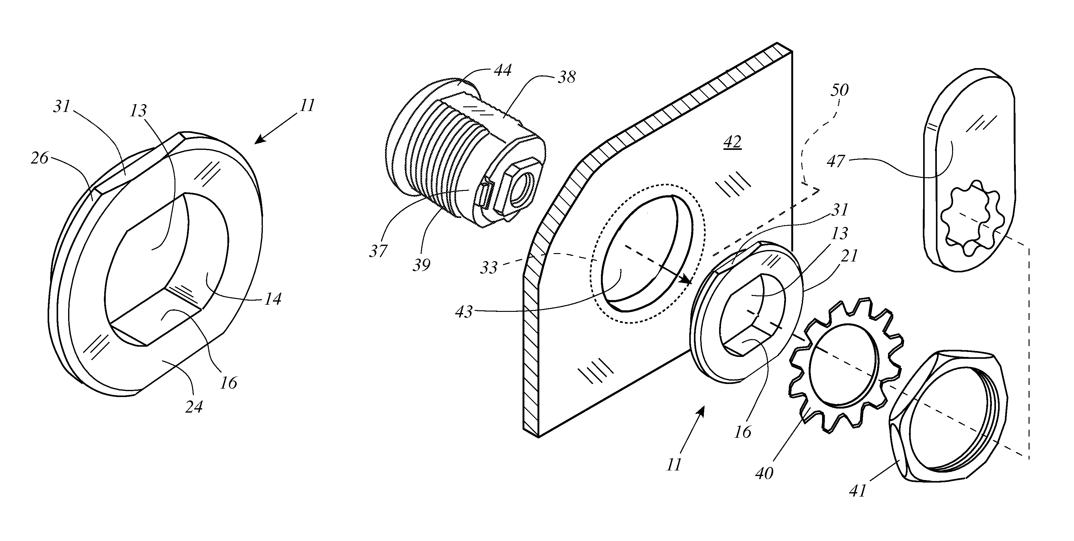
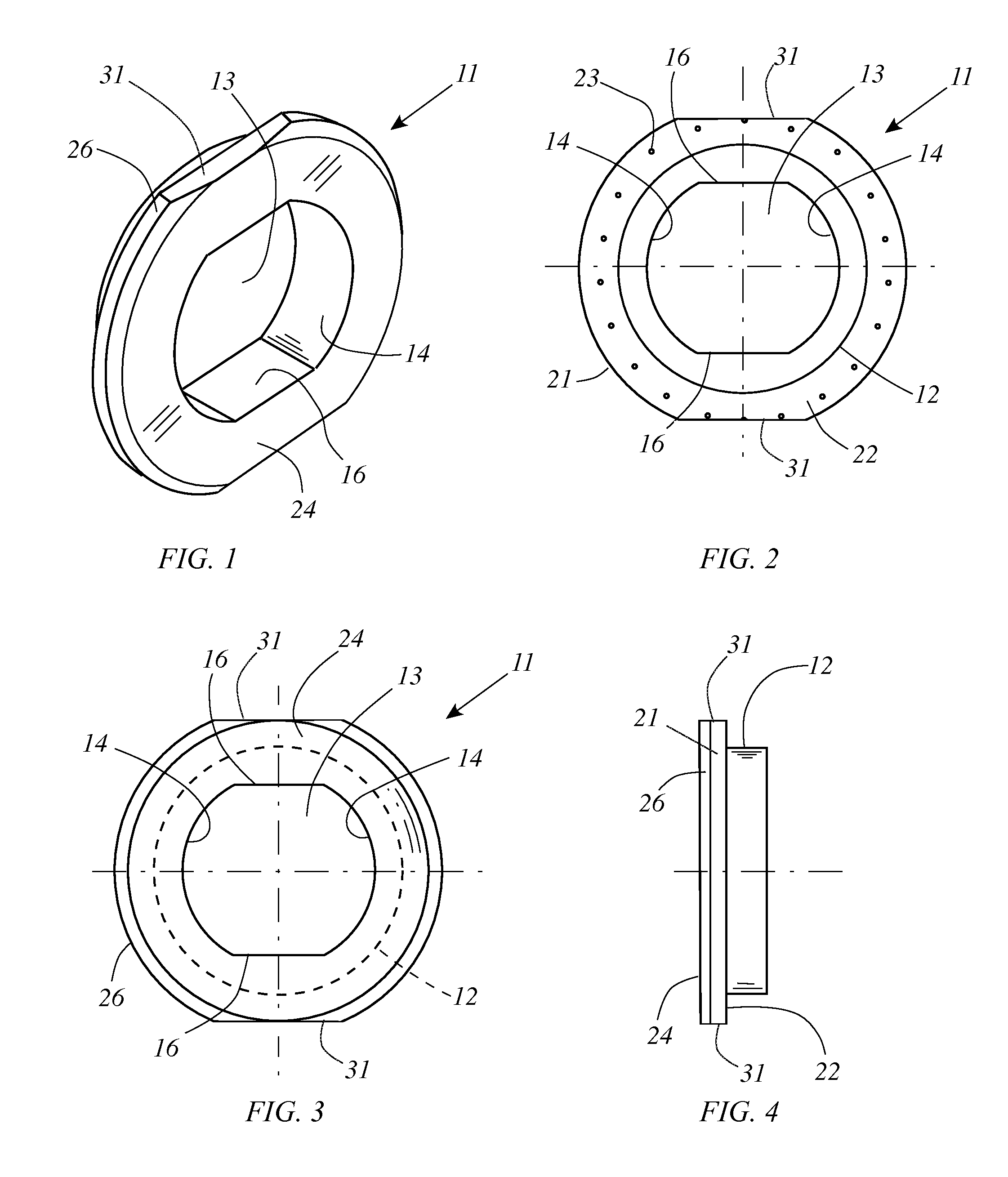
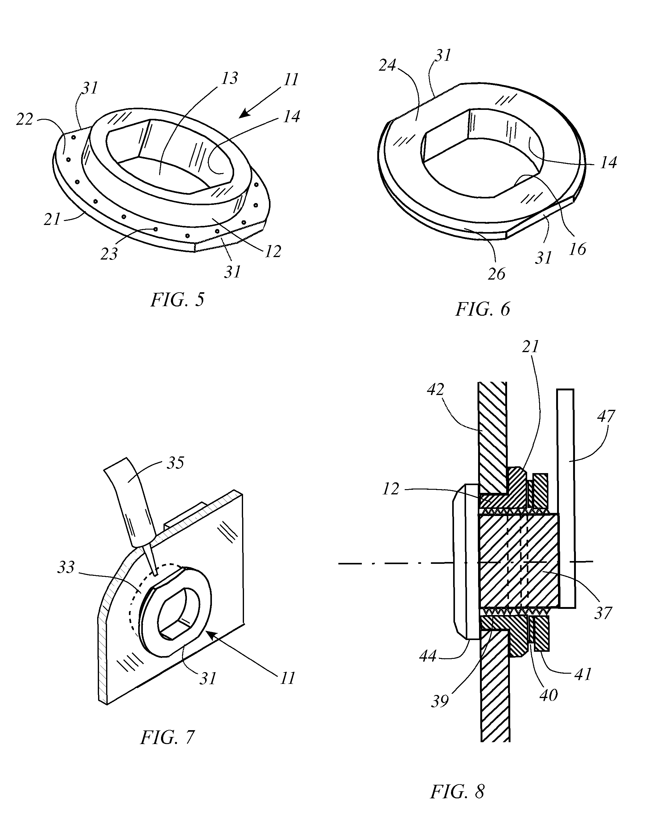
[0022]The present invention generally comprises a hole adapter insert for modifying a circular hole to mount a D / DD lock body securely in a rotationally fixed manner. With regard to FIGS. 1-6, the hole adapter insert 11 includes a disk-like body 12 having a cylindrical outer peripheral surface that is adapted to be received in a lock mounting hole that is also cylindrical and dimensioned with a complementary diameter. A bore 13 extends axially through the body 12, and includes a pair of diametrically opposed curved sidewall portions 14 that are sections of a common cylindrical, joined by a pair of chordally extending sidewall portions 16 that are generally planar, diametrically opposed, and parallel each to the other. The planar sections 16 are disposed to engage the opposite flats of a standard double-D lock body construction that is well known in the prior art, so that a lock body received in bore 13 cannot rotate with respect to the insert 11 about the axis thereof.

[0023]Note tha...


PUM


Abstract

A hole adapter insert for modifying a circular hole to mount a D / DD lock body securely in a rotationally fixed manner includes a disk-like body having a cylindrical outer surface received in the circular hole. A bore extending axially through the body is provided with the requisite standard D / DD cross-sectional profile to receive a standard, complementarily-formed lock body. Extending radially from one end of the body is an annular flange having a proximal face adapted to be glued to the annular surface about the exterior of the circular hole. Alignment flats at the periphery of the flange enable proper D / DD angular alignment of the lock body. A cam lock body is inserted through the outer end of the bore of the insert and secured by a lock nut threaded onto the lock body at the inner end thereof.

Description

CROSS-REFERENCE TO RELATED APPLICATIONS[0001]Not applicableFEDERALLY SPONSORED RESEARCH[0002]Not applicable.SEQUENCE LISTING, ETC ON CD[0003]Not applicable.BACKGROUND OF THE INVENTION[0004]1. Field of the Invention[0005]This invention relates to arrangements for mounting locks and latches and, more particularly, to adapting a circular mounting hole to secure a standard D or double D lock body.[0006]2. Description of Related Art[0007]In the field of locks and latches, there are a great number of products that are used to secure doors, panels and cabinets in low security situations; that is, settings in which there is a need to maintain a closure against casual or incidental opening, but no requirement to resist intentional breaking and entering. A common lock for such uses is a cam lock, in which a lock armature has an arm, or cam extending radially therefrom and arranged to pivot into engagement with a fixed structural element adjacent to a cabinet door, or panel. One consummate exa...

Claims


Application Information

Patent Timeline
IPC IPC(8): A47B95/04F16B43/00
CPCF16B43/00E05C3/042E05B9/084E05B15/1607
Inventor AYREST, ROBERT B.
Owner AYREST ROBERT B
Learn More