
Electrochromic device

a technology of electrochromic material and electrode, which is applied in the direction of optical viewing, instruments, vehicle components, etc., can solve the problems of high power consumption, slow reaction speed upon decolorization, and troublesome electrochromic material in liquid state, so as to achieve uniform discoloration and decolorization, the speed of decolorization reaction is fast, and the power consumption is low

Inactive Publication Date: 2015-06-09
LG INNOTEK CO LTD
View PDF8 Cites 0 Cited by
  • Summary
  • Abstract
  • Description
  • Claims
  • Application Information

AI Technical Summary

Benefits of technology

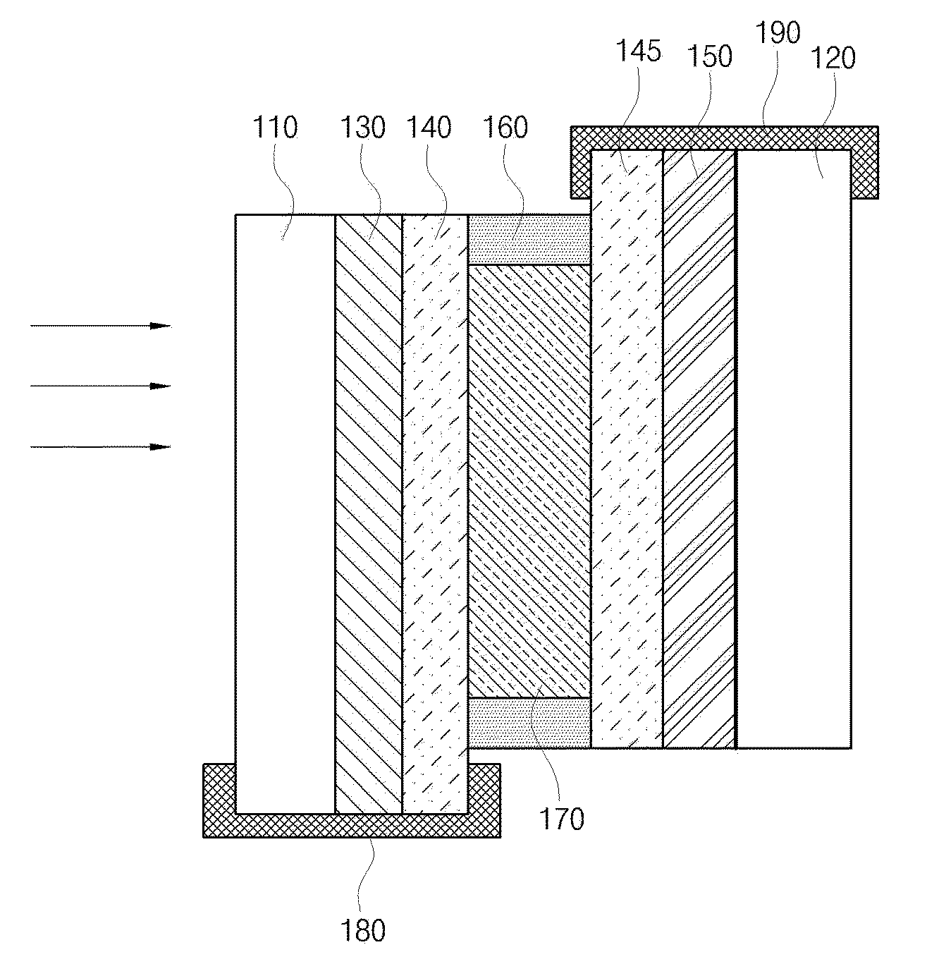
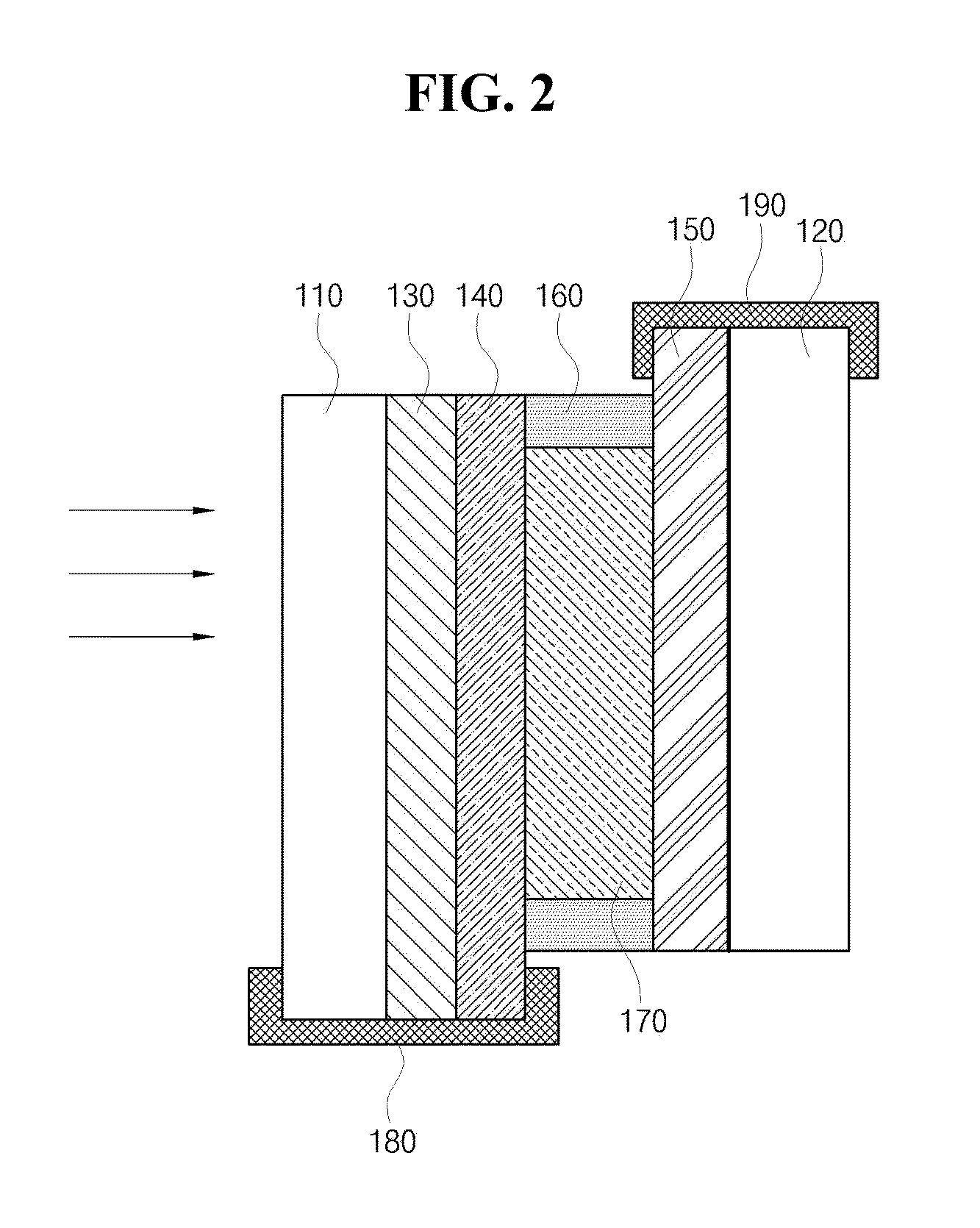
[0011]Accordingly, the present invention has been made keeping in mind the above problems occurring in the related art. An aspect of the present invention provides an electrochromic device, which is configured such that an electrochromic coating layer is formed by coating an electrochromic material on a substrate so that uniform discoloration and decolorization can be performed, and low power consumption and a rapid reaction speed can be realized.
[0014]The advantageous effect according to the embodiments of the present invention is that the electrochromic coating layer coated with the electrochromic material is formed so that uniform discoloration and decolorization can be performed.
[0015]Also, Another advantageous effect according to the embodiments of the present invention is that since the electrochromic material has a memory effect, a voltage is applied only upon discoloration and decolorization, and thus low power consumption is required, and since a reverse voltage is applied upon decolorization, the speed of a decolorization reaction is fast.
[0016]Moreover, since the electrochromic material capable of applying a coating method is an inorganic or organic polymer, durability of the material is excellent.

Problems solved by technology

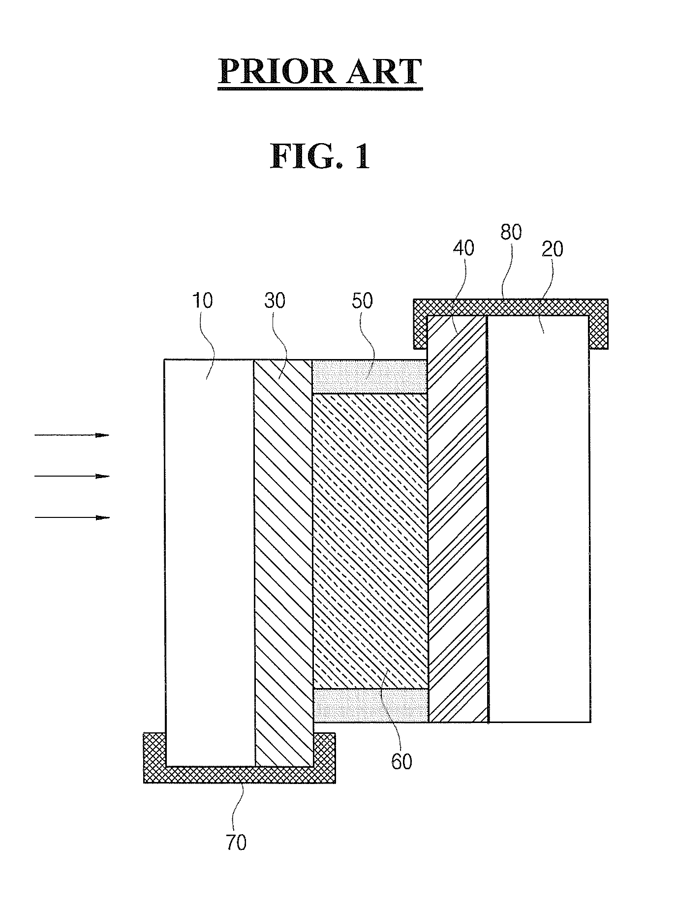
Thus, it is problematic in that high power consumption is required, and a reaction speed is slow upon decolorization.
Furthermore, the electrochromic material in the liquid state is problematic in that uniform discoloration is not performed upon discoloration.

Method used


Image

  • Electrochromic device
  • Electrochromic device
  • Electrochromic device

Examples


Embodiment Construction

[0022]Hereinafter, preferred embodiments of the present invention will be described in detail with reference to the accompanying drawings. In the following description, it is to be noted that, when the functions of conventional elements and the detailed description of elements related with the present invention may make the gist of the present invention unclear, a detailed description of those elements will be omitted. Further, it should be understood that the shape and size of the elements shown in the drawings may be exaggeratedly drawn to provide an easily understood description of the structure of the present invention rather than reflecting the actual sizes of the corresponding elements.

[0023]The gist of the present invention is to provide an electrochromic device, which is configured such that an electrochromic coating layer is formed by coating an electrochromic material on a substrate so that uniform discoloration and decolorization can be performed, and low power consumptio...


PUM

PropertyMeasurementUnit
conductiveaaaaaaaaaa
electrochromicaaaaaaaaaa
transparentaaaaaaaaaa

Abstract

Provided is an electrochromic device including: two substrates opposed to each other; an electrode and a conductive reflection layer interposed between the two substrates; a first electrochromic coating layer interposed between the electrode and the conductive reflection layer; and an electrolyte layer interposed between the first electrochromic coating layer and the conductive reflection layer, whereby uniform discoloration and decolorization can be performed, the efficiency of power consumption can be enhanced, and a durability of the device and the speed of a decolorization reaction can be improved.

Description

CROSS-REFERENCE TO RELATED APPLICATION[0001]This application claims the benefit under 35 U.S.C. §119 of Korean Patent Application No. 10-2012-0069267, filed Jun. 27, 2012, which is hereby incorporated by reference in its entirety.BACKGROUND[0002]1. Field of the Invention[0003]The present invention relates to an electrochromic device, more specifically, to an electrochromic device in which an electrochromic coating layer coated with an electrochromic material is formed so that uniform discoloration and decolorization can be performed.[0004]2. Description of the Related Arts[0005]Electrochromism is a phenomenon in which a color is reversibly changed by the direction of an electric field when a voltage is applied. An electrochromic material is a material, an optical property of which can be reversibly changed by an electrochemical redox reaction having the electrochromism property. The electrochromic material is not colored when an electrical signal is not applied from the outside, but...

Claims


Application Information

Patent Timeline
Patent Type & Authority Patents(United States)
IPC IPC(8): G02F1/155G02F1/157G09G3/38B60R1/08G02F1/15
CPCG02F1/157G09G3/38B60R1/088G02F1/15B60R1/085G02F1/1508G02F1/1523G02F1/155G02F2001/1515G02F2203/02G02F1/15165
Inventor JUN, SUNG GONCHOE, HAE MINSHIN
Owner LG INNOTEK CO LTD
Learn More