Developer accommodating unit, developing device, process cartridge and electrophotographic image forming apparatus
- Summary
- Abstract
- Description
- Claims
- Application Information
AI Technical Summary
Benefits of technology
Problems solved by technology
Method used
Image
Examples
first embodiment
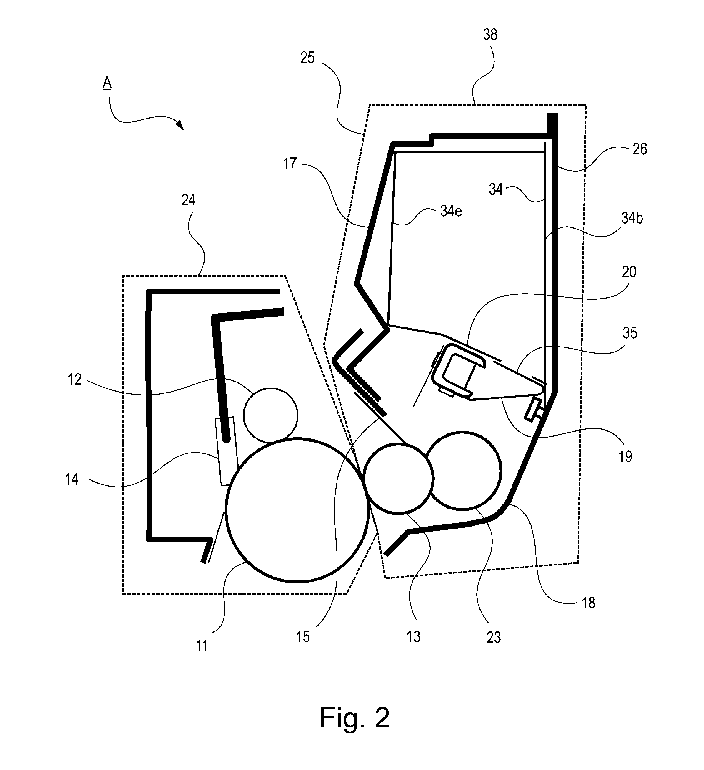
[0028]FIG. 2 is a principal sectional view of a process cartridge including the developer accommodating unit to which the present invention is applicable, and FIG. 3 is a principal sectional view of an electrophotographic image forming apparatus to which the present invention is applicable.
[0029]The process cartridge includes an image bearing member, which is an electrophotographic photosensitive member, and process means acting on the image bearing member and is detachably mountable to the image forming apparatus. Examples of the process means include a charging means for electrically charging a surface of the image bearing member, a developing device for forming an image on the image bearing member, and a cleaning means for removing a developer (toner, carrier, etc.) remaining on the image bearing member surface.
[0030]The process cartridge A in this embodiment includes, as shown in FIG. 2, includes a photosensitive drum 11 as the image bearing member and includes, at a periphery o...
second embodiment
[0063]Second Embodiment will be described. In this embodiment, a constitution different from the constitution of the unsealing member 20 in First Embodiment is employed, and in this embodiment a different portion of the constitution different from that in First Embodiment will be described and thus the same constitution portion (another portion) will be omitted from the description.
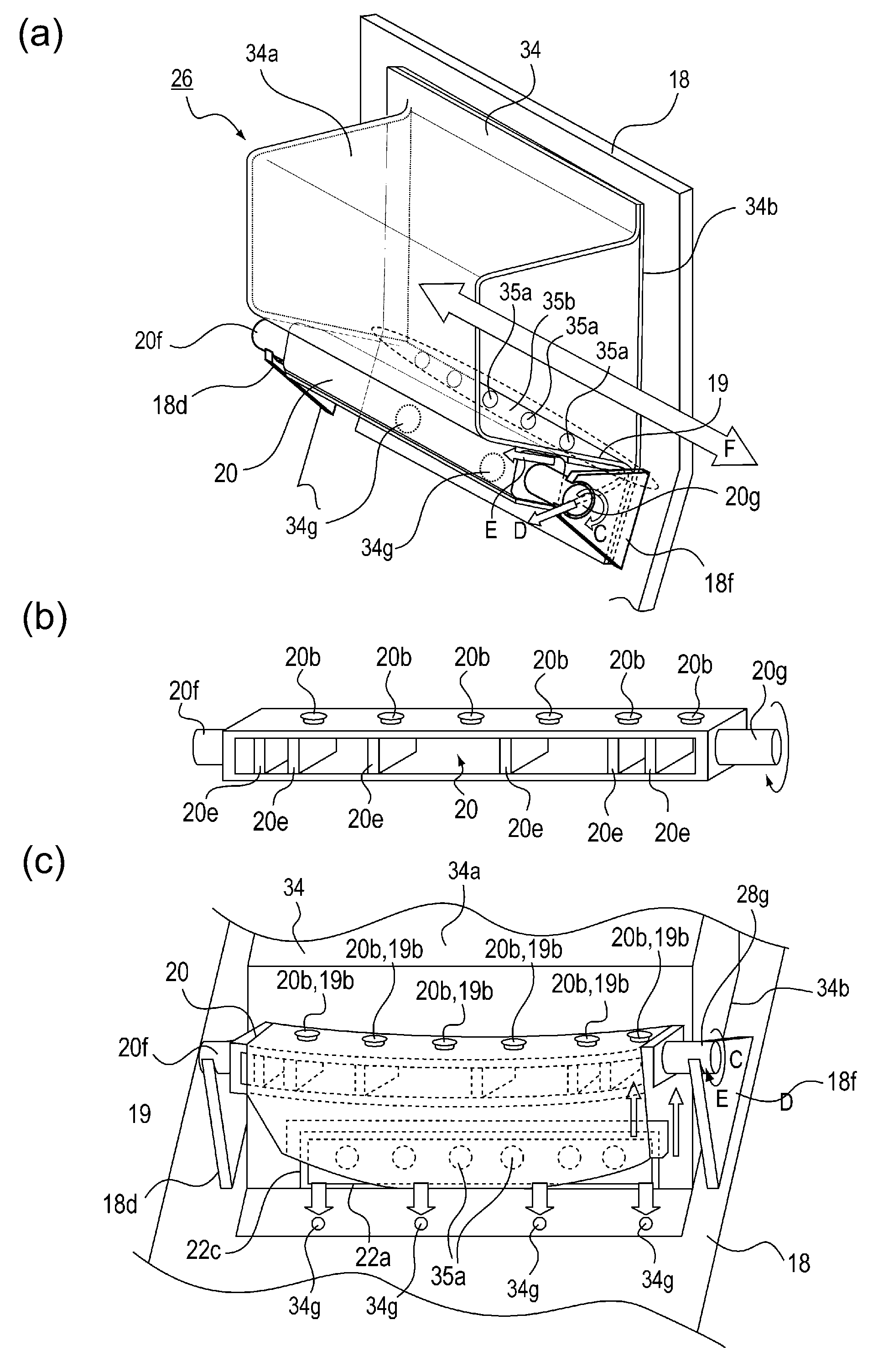
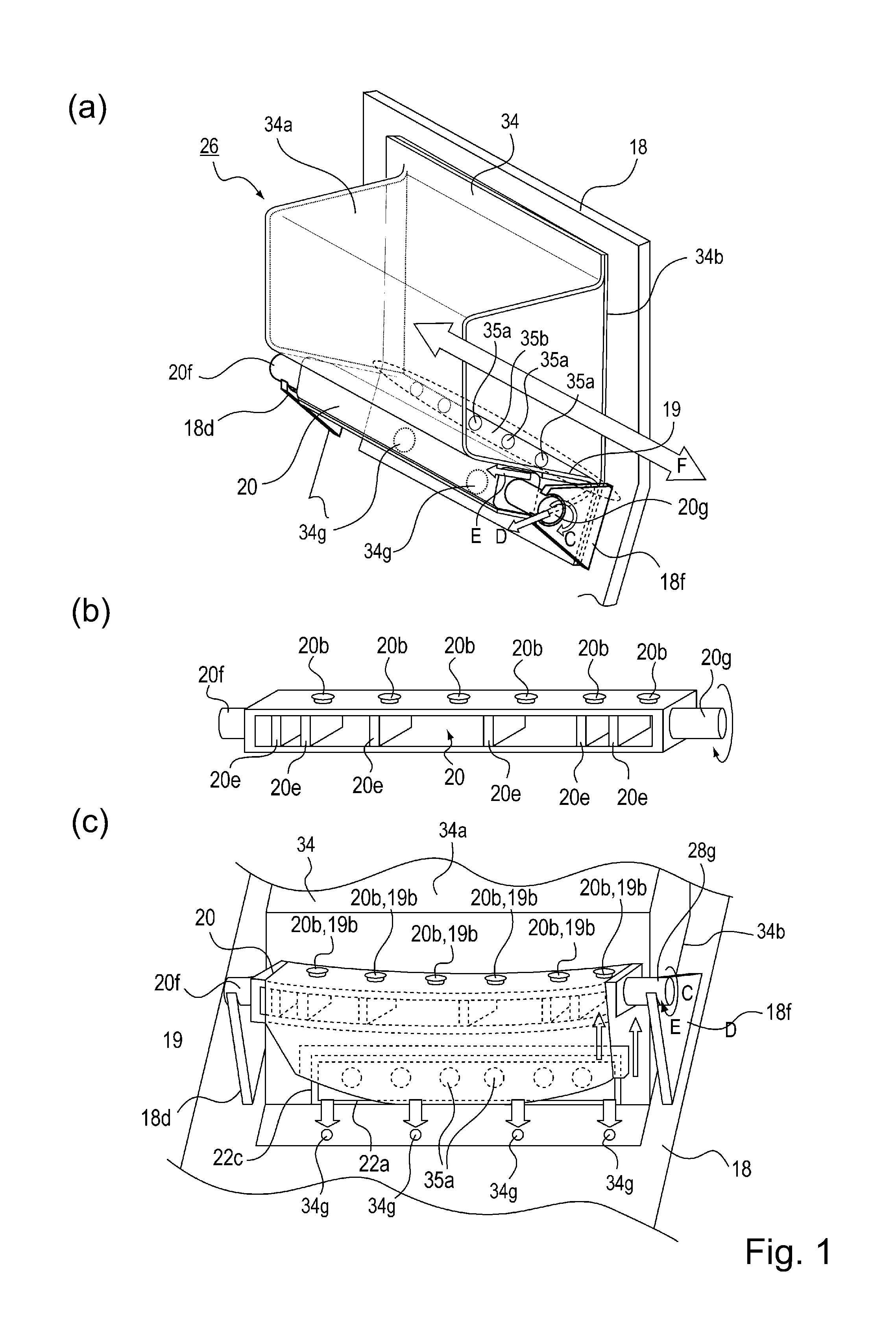
[0064]Parts (a) and (b) of FIG. 10 are illustrations each showing the unsealing member 20 and its peripheral portion. Part (a) of FIG. 10 is a perspective view showing an arrangement relationship among the unsealing member 20, the discharging portion 35, the sealing member 19 and the supporting portion 18d provided on the second frame 18. Part (b) of FIG. 10 is an illustration showing a structure of the unsealing member 20.
[0065]The unsealing member 20 in this embodiment has, as shown in (b) of FIG. 10, a so-called D-cut shape such that a cross section with respect to an axial direction has a single flat ...
third embodiment
[0077]In the above-described embodiments, the case where the developer accommodating member for accommodating the developer is the flexible container is illustrated, but the developer accommodating member is also applicable even when the developer accommodating member has no flexibility.
[0078]FIG. 13 is a sectional view showing a structure in which the developer accommodating member 34 having the flexibility is not used. As shown in FIG. 13, the developer is directly accommodated in a space defined by the first frame 17 and the second frame 18, and therefore the developer accommodating member is constituted by the first frame 17 and the second frame 18. Further, a constitution in which the first frame 17 is provided with an opening 35a constituting the discharging portion 35 of the developer, and the sealing member 19 for sealing the opening 35a is bonded to the first frame 18, which is a rigid member, via the connecting portion 22 is employed.
[0079]Further, the sealing member 19 is...
PUM
 Abstract
Description
Claims
Application Information
 - R&D
- Intellectual Property
- Life Sciences
- Materials
- Tech Scout
- Unparalleled Data Quality
- Higher Quality Content
- 60% Fewer Hallucinations
Browse by: Latest US Patents, China's latest patents, Technical Efficacy Thesaurus, Application Domain, Technology Topic, Popular Technical Reports.
© 2025 PatSnap. All rights reserved.Legal|Privacy policy|Modern Slavery Act Transparency Statement|Sitemap|About US| Contact US: help@patsnap.com


