Control system with displaceable knob

a control system and knob technology, applied in the direction of mechanical control devices, manual control with single controlling member, instruments, etc., can solve the problems of knobs not being operated, unsatisfactory for users, accuracy and user perception problems, etc., and achieve the effect of simplifying the user

Active Publication Date: 2015-06-09
APTIV TECH LTD
View PDF13 Cites 7 Cited by
  • Summary
  • Abstract
  • Description
  • Claims
  • Application Information

AI Technical Summary

Benefits of technology

[0010]The present invention resolves the problem mentioned above by proposing a mechanical control unit provided with a return means such that the forces are small in neutral positions and increase rapidly upon operation.
[0015]The lever extends outside the case through an opening in the shape of a cross so that the pivotings of the lever are limited by the branches of the cross. Thus, the cross offers the advantage of simpler function selection without risk of confusion.
[0017]Also, in the neutral position the faces of the case and of the knob facing one another are distant one from the other so that the knob can be depressed in the direction of the case. In the pivoted position of the lever, the faces of the case and of the knob facing one another are in contact one with the other so that the knob cannot be depressed in the direction of the case. The non-combination of the functions is an advantage in that it represents a considerable simplification for the user.

Problems solved by technology

Thus, without any operation, the knob returns by itself into a neutral position, it has no perceptible operating play which would be very unpleasant for the user and its displacements are always accompanied by return forces perceived by the user.
A known problem of the proposed mechanisms is associated with the fact that for the great majority of the time the knobs are not operated and remain in the neutral position.
Thus, ageing by non-use causes local deformations that can produce problems with accuracy and the perception of the user.
The strong materials are more costly and generally more difficult to work, while the reduction of forces causes a “limpness” in use and unacceptable inaccuracies with regard to the elastic return or the maintenance of the knob in the neutral position.

Method used


Image

  • Control system with displaceable knob
  • Control system with displaceable knob
  • Control system with displaceable knob

Examples


Embodiment Construction

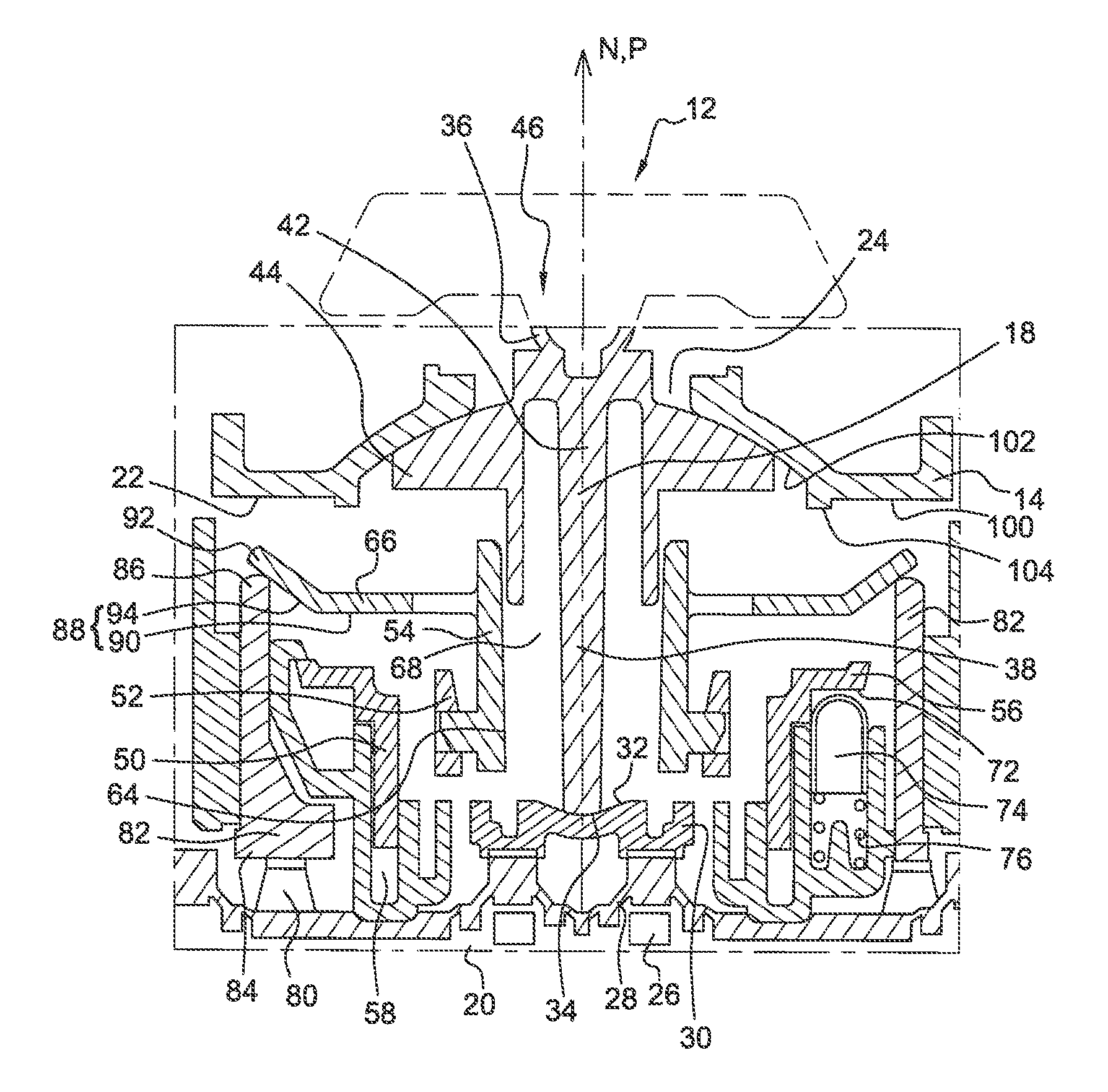
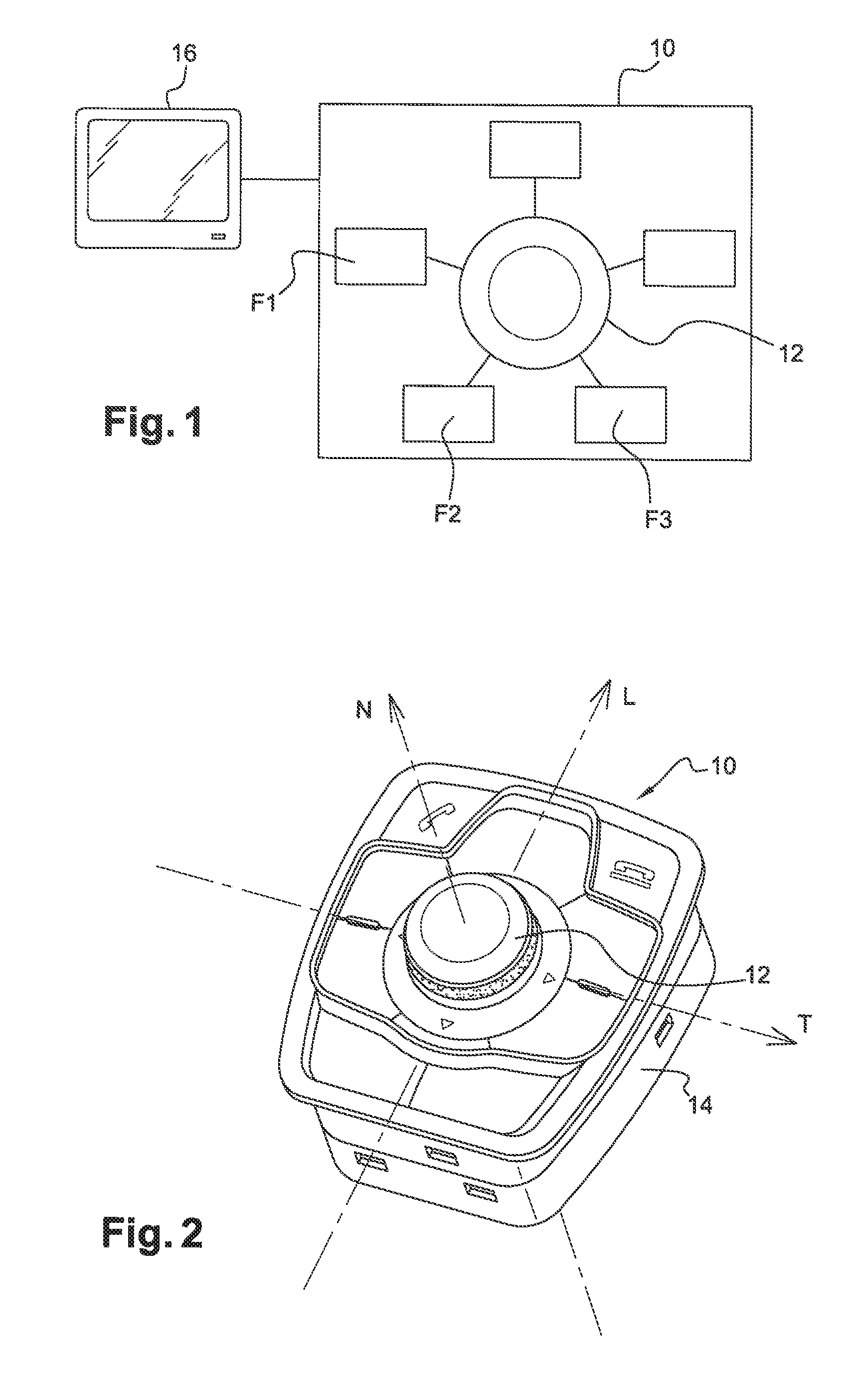
[0027]A control system 10 such as shown diagrammatically in FIG. 1 allows a user who acts on a knob 12 linked to a case 14 to act on various functions F1, F2, F3 . . . of the vehicle. The user can observe the state of the controls F1, F2, F3 . . . on a monitoring screen 16.

[0028]The control system 10 formed in accordance with the invention is presented in FIG. 2. The knob 12, accessible to an occupant, is orientated depending on the chosen location in the vehicle.

[0029]FIG. 2 shows the system 10 referenced in a system of straight perpendicular axes comprising a longitudinal axis L, a transversal axis T and a neutral axis N fixed relative to the case 14. The knob 12 is shown surrounded by buttons for selection of specific controls. Alternatively, the system 10 can have no buttons and only comprise the knob 12.

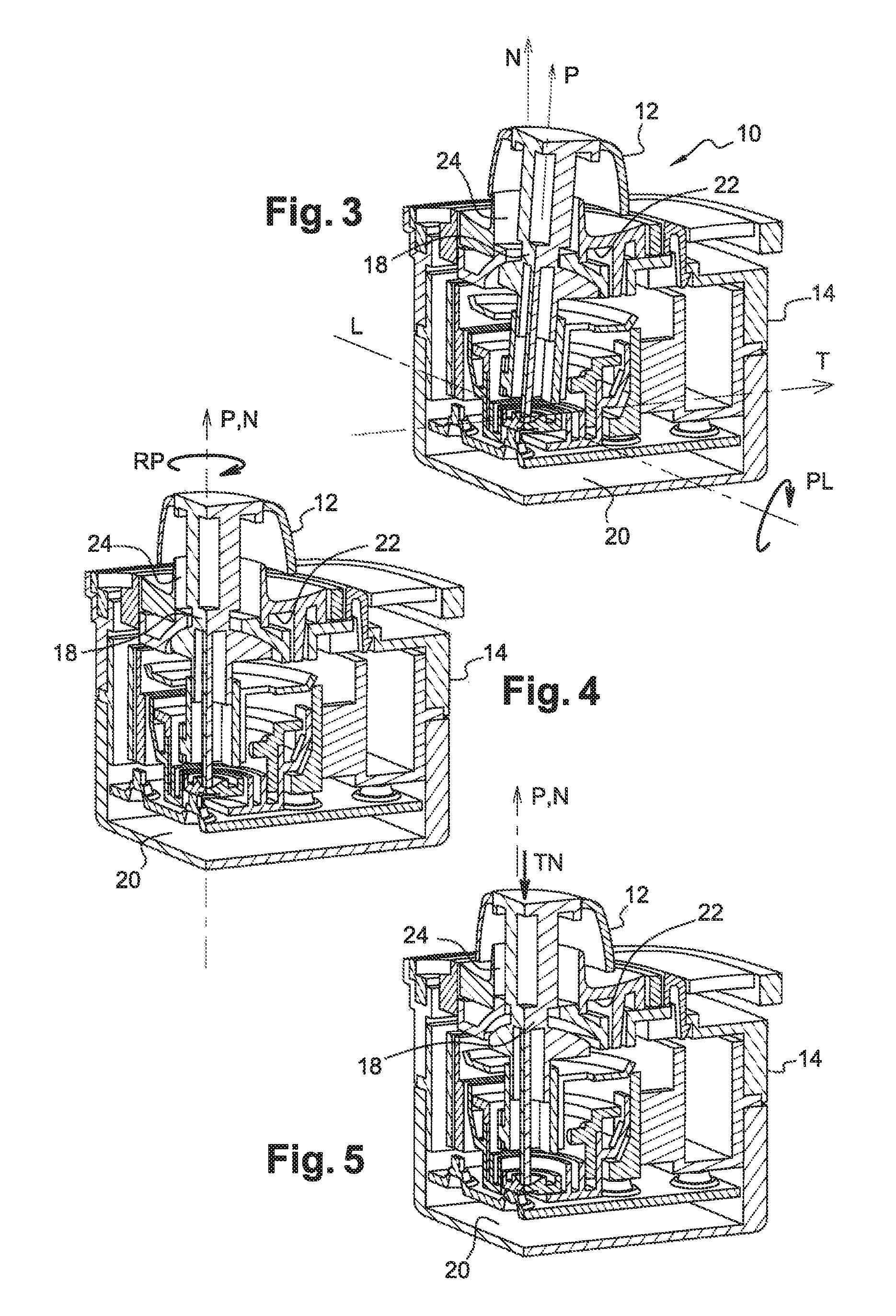
[0030]As shown by the succession of FIGS. 3, 4 and 5, and without detailing the structure of the system 10, the knob 12, mounted at the end of a lever 18 can from a neutral posi...


PUM


Abstract

Control system intended for the choice and the selection of functions in a vehicle, the system comprising a case, a lever extending along a main axis from a first end, mounted pivoting about a pivot axis to a second end provided with an actuation knob, the lever being able to turn about the main axis, and an elastic return device of the lever into a neutral position comprising an action surface in the form of a truncated cone of revolution, the axis of which is the main axis and, on a pivoting of the lever, the active zone is displaced along a generatrix of the cone moving towards the vertex, the elastic means being more biased than in a neutral position.

Description

CROSS-REFERENCE TO RELATED APPLICATION[0001]This application claims the benefit under 35 U.S.C. §371 of published PCT Patent Application Number PCT / EP 2011 / 066642, filed Sep. 26, 2011, claiming priority to French patent application number FR1057870 filed on Sep. 29, 2010, and published as WO2012 / 041798 on Apr. 5, 2012, the entire contents of which is hereby incorporated by reference herein.TECHNICAL FIELD OF INVENTION[0002]The invention relates to a control system with displaceable knob used in motor vehicles as a digital control interface.BACKGROUND OF INVENTION[0003]The multiplicity of controls to which the driver of a modern vehicle has access is such that numerous interfaces are developed allowing activation of the functions without having to look at the control or his hands. The user relies on digital feel alone to control a function and can thus keep his eyes concentrated on the road. Among other digital interfaces, directional knobs placed at the central console between the f...

Claims


Application Information

Patent Timeline
Patent Type & Authority Patents(United States)
IPC IPC(8): H01H25/06G05G9/047G05G9/02B60K37/06
CPCH01H25/065G05G9/047B60K37/06G05G9/02B60K2350/1048B60K2350/35Y10T74/20201B60K2350/102B60K2370/137B60K2370/50B60K2370/126B60K2370/135
Inventor KREIDER, JULIENCOLLIN, EMILIE
Owner APTIV TECH LTD
Why Eureka
Try Eureka