Loading and unloading station

a technology for unloading stations and cassettes, which is applied in the direction of lifting frames, lifting devices, cabinets, etc., can solve the problems of requiring a lot of height direction space for apparatuses, forklifts and forklift forks, etc., and achieves the effect of facilitating the operation of other devices, reducing the placement of lifting and transfer devices, and improving the rigidity of cassettes

Active Publication Date: 2015-06-16
FASTEMS
View PDF18 Cites 0 Cited by
  • Summary
  • Abstract
  • Description
  • Claims
  • Application Information

AI Technical Summary

Benefits of technology

[0009]The supporting arm for lifting the supporting beam, and the mechanism for lifting the supporting arms, are primarily placed under the supporting beam and in the space limited by the supporting beam so that the fork of a forklift has as much space as possible between the supporting beams. When pivoting, the supporting arms are turned in a direction that is parallel with both the elongated supporting beam and the fork of the forklift, wherein the supporting arms do not collide with the fork. The cassette is a separate, self-contained part with respect to the station. The cassette only needs an opening for the supporting beam, because the supporting beams are placed in their different positions under the supporting beam, so that the openings of the cassette can be kept small and the rigidity of the cassette is improved. The supporting beam can also be placed close to the end of the station and the cassette, wherein, for example, the end of the sheet and the outermost pallet are supported to a sufficient degree.
[0010]In combination with the cassette, the station also becomes low, wherein the lifting and transfer devices of the storage can be placed as low as possible, and thereby more cassettes can be placed on top of each other in the storage. The low placement of the lifting and transfer devices also entails other advantages, and their functioning with other devices is facilitated. Thanks to the low structure, the station can be placed at such a height level that a forklift with front idlers can be applied. In this case, the idlers of the forklift can roll under the station, and the fork is above the station or between the supporting beams. Furthermore, the actuators, legs or wheels of the station and other structures and actuators can be placed so that they are fitted between the idlers of the forklift, when the forklift is applied to manipulate a separate pallet to be placed at an end of the station.

Problems solved by technology

One problem is that the vertically moving bars require a lot of space in the height direction, in which case the station becomes unnecessarily high, wherein the use of a forklift and the fork of the forklift may be problematic, and the apparatus requires a lot of space in the height direction.
Furthermore, there is a risk that when pivoting in the lateral direction, said bars collide with the fork which is parallel to the width direction of the station.

Method used


Image

  • Loading and unloading station
  • Loading and unloading station
  • Loading and unloading station

Examples


Embodiment Construction

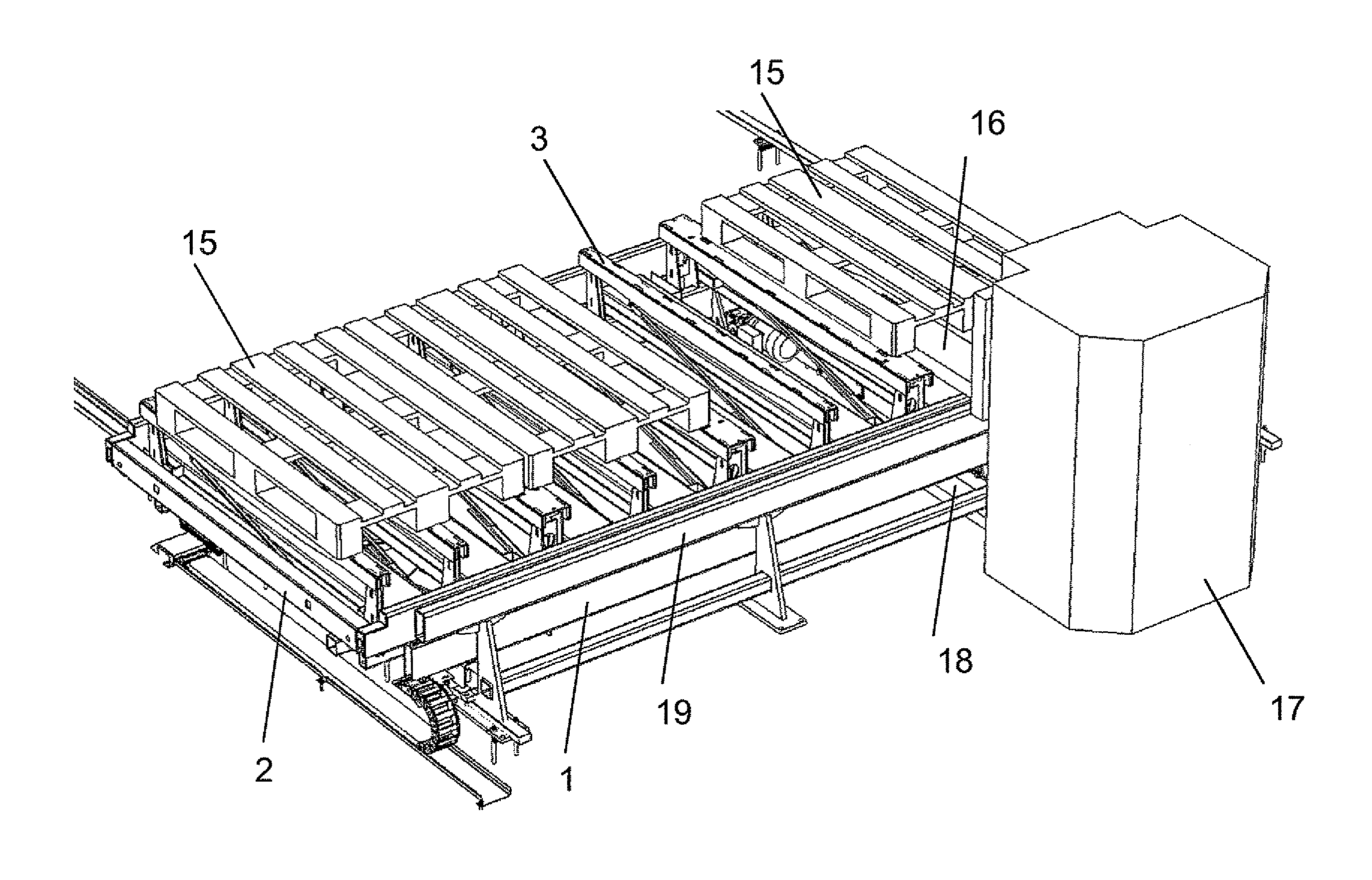
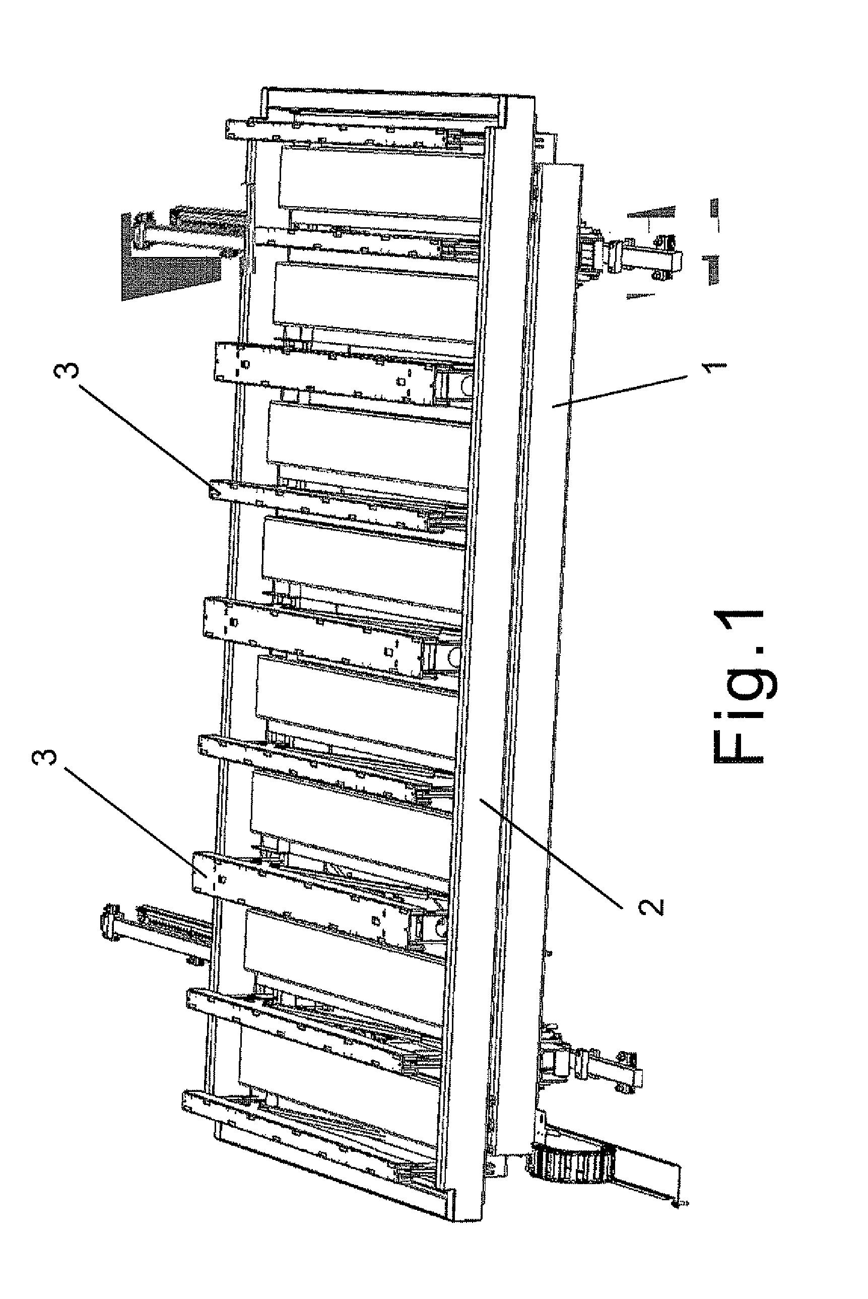
[0021]In FIG. 1, a loading and unloading station, which is also called a station in this description, is shown together with a cassette 2. The station comprises a frame 1, which is normally a square or rectangular horizontal framework, provided with the necessary mechanisms and actuators. In this example, wheels or rolls are coupled under the frame 1, by means of which the station can be transferred along rails or a corresponding track. In this example, the frame 1 can be transferred in a direction parallel to the short side of the station, but alternatively, the direction of transfer may also be parallel to the long side of the station.

[0022]A separate cassette 2 can be lowered on top of the frame 1. Typically, this is performed so that a lifting and transfer device grasps under both ends of the cassette 2 and performs the desired transfers. The length of the frame 1 as well as the placement of the mechanisms and the actuators are selected so that the lifting and transfer device ha...


PUM

PropertyMeasurementUnit
horizontal distancesaaaaaaaaaa
heightaaaaaaaaaa
external forceaaaaaaaaaa

Abstract

A loading and unloading station, comprising: a frame, on top of which a cassette intended for the carrying and storage of loads can be placed; at least two supporting arms connected to the frame in a pivotable manner so that the supporting arms can pivot around substantially horizontal pivot axes to a substantially horizontal position, in which the supporting arms are placed under the cassette, and to a substantially vertical position, in which the supporting arms extend through the cassette; at least one supporting beam, on top of which the load can be placed and to which the at least two supporting arms are connected in a movable manner; and the supporting arms are fitted both to lift the supporting beam from below the cassette through the cassette above the cassette, and to lower the supporting beam back under the cassette; and the supporting arms are further fitted to keep the supporting beam substantially horizontal.

Description

FIELD OF THE INVENTION[0001]The invention relates to a loading and unloading station. The loading and unloading station is used in the manipulation of loads, such as sheets, sheet material or pallets, when loads are transferred into a cassette for storage, or away from it.BACKGROUND OF THE INVENTION[0002]Sheets are often manipulated by means of cassettes, in which cassettes one or several sheets are held in the horizontal position and on top of each other. By means of the cassettes, the sheets are held in a storage, which is, for example, a high rise storage or a shelf system, in which the cassettes are placed. A cassette is presented in publication EP 1582481 A1. The cassettes are fed into the storage and delivered from the storage by using a separate station, by means of which the sheets can be delivered to the cassette or removed from the cassette, for example by means of the fork of a forklift. The station comprises a kind of a table which is fixed to be stationary or, in the no...

Claims


Application Information

Patent Timeline
Patent Type & Authority Patents(United States)
IPC IPC(8): H01L51/56B65G65/00B66F7/06
CPCB65G65/00B66F7/0633B65H2301/42254B65H2301/42256B65G1/04
Inventor MALVISALO, JANI MVARTIAINEN, TERO T
Owner FASTEMS
Why Eureka
Try Eureka