Offset conduit body

a conduit body and offset technology, applied in the direction of branching pipes, electrical equipment, mechanical equipment, etc., can solve the problems of conduit body, conduit body, laborious work of wire fitting to prior art conduit body and junction point,

Active Publication Date: 2015-06-16
GOSSE ROBERT
View PDF21 Cites 4 Cited by
  • Summary
  • Abstract
  • Description
  • Claims
  • Application Information

AI Technical Summary

Benefits of technology

[0011]With the novel L-type conduit body the difference with the prior art is that the two pieces of conduit connected thereto do not lie in the same plane. There is a vertical offset between one of the two conduits and the other of the two conduits. The

Problems solved by technology

However, due to the often heavy gauge of the wiring, the wires often become tangled or are difficult to bend in order to fit into the conduit body.
Since wiring without a proper junction point is in violation of safety codes for almost all types of construction, the labor intensive work of fitting the wires to the prior art conduit body and junction point is required.
Where an LB type conduit body is involved, the most labor intensive part of fitting the conduit body is the bending of wire/conduit through a sharp 90° turn within the confines of th

Method used


Image

  • Offset conduit body
  • Offset conduit body
  • Offset conduit body

Examples


Embodiment Construction

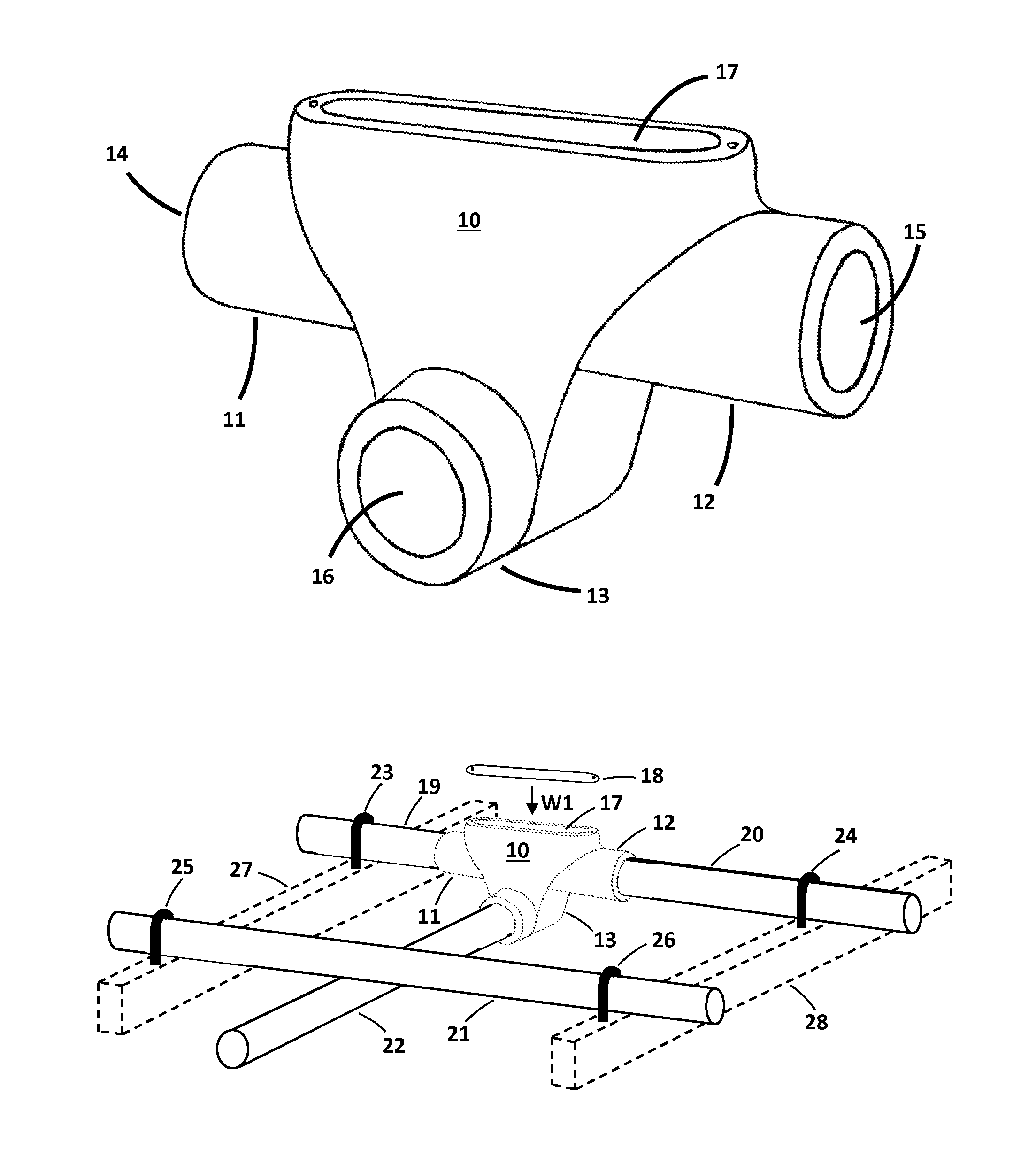
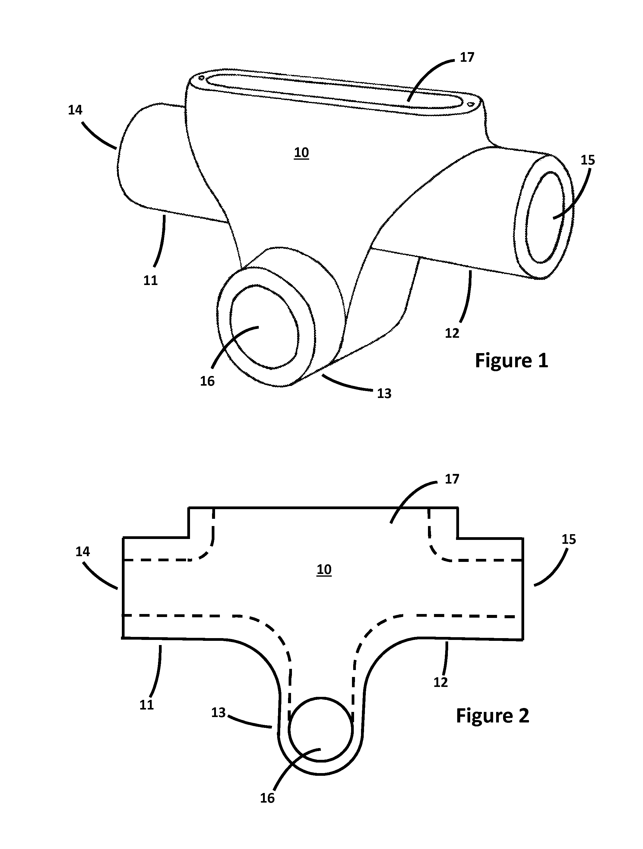
[0024]FIG. 1 is a three dimensional view of a T-type conduit body 10 of the present invention. There can be second variant of this T-type conduit body 10, not shown, where offset conduit port 13 of the conduit body 10 points in the opposite direction from that shown in FIG. 1.

[0025]The T-type conduit body 10 shown in FIG. 1 has a left conduit port 11, a right conduit port 12, and an offset conduit port 13 that does not lie in the same plane as co-linear conduit ports 11 and 12. Offset conduit port 13 faces in a direction that is perpendicular to the common axis of conduit ports 11 and 12, alike the prior art, but is offset in the downward direction as shown, which is not done in the prior art. The purpose of the offset will be better understood in viewing FIGS. 2 and 6 and reading the description for those figures. Alike prior art conduit bodies there is a conduit body access hole 17 that is used to access the interior of conduit body 10 for pulling wires through conduit connected t...


PUM


Abstract

The invention is a novel offset conduit body that has T-type, L-type and X-type conduit body variants. The T-style conduit body has an offset port the axis of which is perpendicular to the co-linear axis of the other two ports, but the axis of the offset port does not lie in a common plane with the axis of the other two ports, and this offset eliminates the need for bending conduit connected to the offset port in order for that conduit to pass over or under different conduit that is adjacent to the T-style conduit body and is parallel to the conduit connected to the other two ports. The L-style conduit body has a first and an offset port oriented at right angles to each other and the axis of the two ports are offset from each other so they do not lie in a common plane, and the offset eliminates the need for bending conduit connected to the offset port in order for that conduit to pass over or under adjacent conduit that is parallel to the conduit connected to the first port. The X-type conduit body has two collinear ports in one plane and two collinear ports in an offset plane.

Description

FIELD OF THE INVENTION[0001]This invention relates to fittings and boxes for electrical wiring and conduits, and more particularly to an electrical conduit body for joining 90° runs of conduit and wiring.BACKGROUND OF THE ART[0002]In a typical commercial electrical construction application, conduit is installed first within a raceway and the conduit houses and protects the wiring. A component known as a conduit body is used at the junction of two or more conduits to join the conduits together. The conduit body has a removable cover to provide access to the interior. A conduit body that provides for a 90° juncture or bend in the conduit and wiring is known as an L-type conduit body. A conduit body that provides for a juncture of three conduits is known as an T-type conduit body. When the conduit and wiring is diverted through an opening opposite the cover, the conduit body is known as an LB conduit body. When the conduit and wiring is diverted 90° through the left side or the right s...

Claims


Application Information

Patent Timeline
IPC IPC(8): F16L41/02
CPCF16L41/02H02G3/0481H02G3/06
Inventor GOSSE, ROBERT
Owner GOSSE ROBERT
Why Eureka
Try Eureka