System and method for mechanical runout measurement

a technology of mechanical runout and measurement system, which is applied in the direction of measuring devices, instruments, using electrical means, etc., can solve the problems of requiring a great deal of time and cost for the entire workpiece, and achieve the effect of reducing the cost and difficulty of measuring mechanical runout on slow roll

Inactive Publication Date: 2015-11-26
GENERAL ELECTRIC CO
View PDF0 Cites 5 Cited by
  • Summary
  • Abstract
  • Description
  • Claims
  • Application Information

AI Technical Summary

Benefits of technology

[0008]To minimize cost and difficulty of measuring slow roll mechanical runout, a mechanical runout measurement system is disclosed that includes: a mount for a work piece, wherein the mount is configured to rotate the work piece; a displacement sensor adjacent a surface of the work piece, at a known position relative to the mount and configured to measure a radial dimension of the work piece; a removable angle indicator attached to the work piece and aligned such that the angle indicator is sensed by the displacement sensor during rotation of the work piece, and a computer system including a non-transitory memory which stores instructions that, when performed, cause the computer to: collect radial displacement data from the displacement sensor adjacent to the work piece as the work piece rotates, wherein the radial displacement data indicates a radial dimension of a surface of the work piece sensed by the displacement sensor; detect a portion of the radial displacement data representing the angle indicator in the collected radial displacement data; set an angular starting point at the portion; and correlate each point of the radial displacement data with an angular location relative to and based on the angular starting point to determine a rotational position for the collected radial displacement data of the work piece relative to the angle indicator.

Problems solved by technology

Measuring a radius at each circumference along the length of an entire work piece often requires a great deal of time and cost, primarily associated with labor.

Method used


Image

  • System and method for mechanical runout measurement
  • System and method for mechanical runout measurement
  • System and method for mechanical runout measurement

Examples


Embodiment Construction

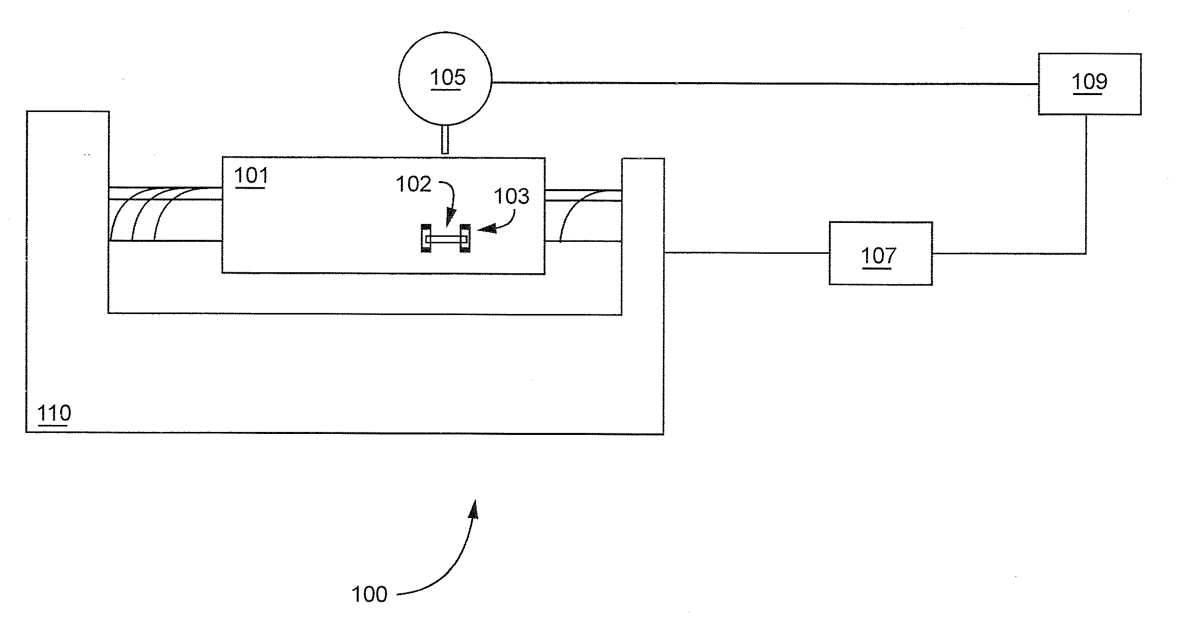
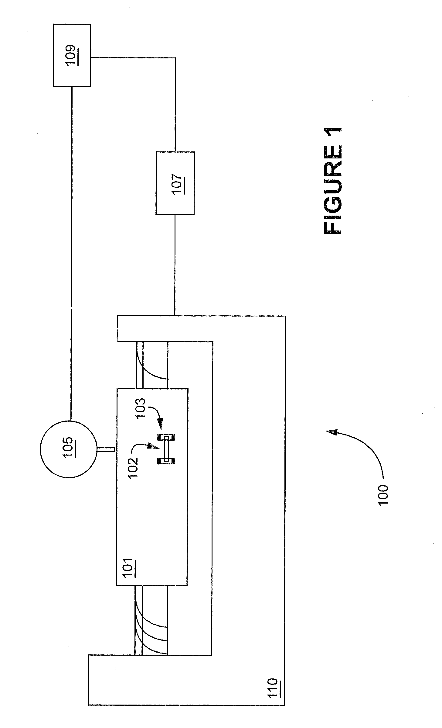
[0018]The present invention relates to the inclusion of a purposefully created temporary artifact on a rotating work piece. Data indicating the artifact is included in sampled data concerning the roundness of the work piece. The sampled data is analyzed to identify a reference point, provided by the artifact, for all of the data sampled around the circumference of the work piece during rotation. While in the past such an artifact, if permanent, would be considered a flaw and reduce the value of the work piece, a purposely created temporary artifact allows a computer system to recognize and assign a zero degree point to 360 degrees worth of data taken at each radial slice of the work piece.

[0019]Such a reference point makes it possible to correlate collected sampled data regarding the roundness of the work piece to specific locations on the work piece while the work piece is still mounted on a mount, for example, a test station, a turbine casing, or workstation. A technician can meas...


PUM


Abstract

A method of measuring mechanical runout including: mounting a work piece on a rotatable mount, wherein the mount is configured to rotate the work piece; placing a displacement sensor at a known position adjacent a surface of the work piece, the displacement sensor being configured to measure a radial dimension of the work piece; attaching a removable angle indicator to the surface of the work piece; rotating the work piece while mounted on the mount and collecting rotational data of the rotational position of the work piece during the rotation; collecting displacement data from the displacement sensor as the work piece rotates, wherein the displacement data indicates a radial distance from a rotational axis of the work piece to the surface of the work piece at points on the surface as the surface rotates with respect to the displacement sensor; analyzing the displacement data to detect data representing the angle indicator on the surface of the work piece; correlating the displacement data with the rotational data, and determining displacements of points on the surface of the work piece based on the correlated displacement data.

Description

BACKGROUND OF THE INVENTION[0001]The invention relates to measuring mechanical runout of a rotating work piece.[0002]A uniform radius is desirable around the circumference of rotating work pieces such as the rotor work piece of a turbine. Knowing the shape of a work piece relative to ideal roundness may be used to compensate for or reduce vibration induced by rotation of the work piece. Measuring a radius at each circumference along the length of an entire work piece often requires a great deal of time and cost, primarily associated with labor.[0003]“Runout”, generally, is the amount of deviation from a desired rotation radius of a rotor during operation, and can be described in terms of mechanical runout and electrical runout. The mechanical runout of a rotor is the deviation from an ideal circular geometry of the rotor plane during rotation. Accurate measurement of the mechanical runout is necessary to be able to minimize the negative impact of these imperfections on performance, ...

Claims


Application Information

Patent Timeline
Patent Type & Authority Applications(United States)
IPC IPC(8): G01D5/14
CPCG01D5/14G01B11/2408G01B11/026G01B7/023G01B7/312G01B21/12G01B21/20
Inventor JIANG, JIELUO, HUAGENG
Owner GENERAL ELECTRIC CO
Why Eureka
Try Eureka