Machining systems comprising a machining facility and control methods

a technology of machining facility and control method, which is applied in the direction of program control, electric programme control, instruments, etc., can solve problems such as difficulty in observation of machining, and achieve the effect of minimizing observation difficulties

Active Publication Date: 2016-11-10
SAFRAN LANDING SYSTEMS
View PDF1 Cites 4 Cited by
  • Summary
  • Abstract
  • Description
  • Claims
  • Application Information

AI Technical Summary

Benefits of technology

[0010]An object of the present invention is to provide a machining system enabling the operator to observe the machining while minimizing the difficulties of observation that are associated with material being projected during machining, such as projections of swarf or of cooling fluid.

Problems solved by technology

Because a large amount of material is projected during machining, the video image picked up by the camera is often degraded, making it difficult to observe the machining.

Method used


Image

  • Machining systems comprising a machining facility and control methods
  • Machining systems comprising a machining facility and control methods
  • Machining systems comprising a machining facility and control methods

Examples


Embodiment Construction

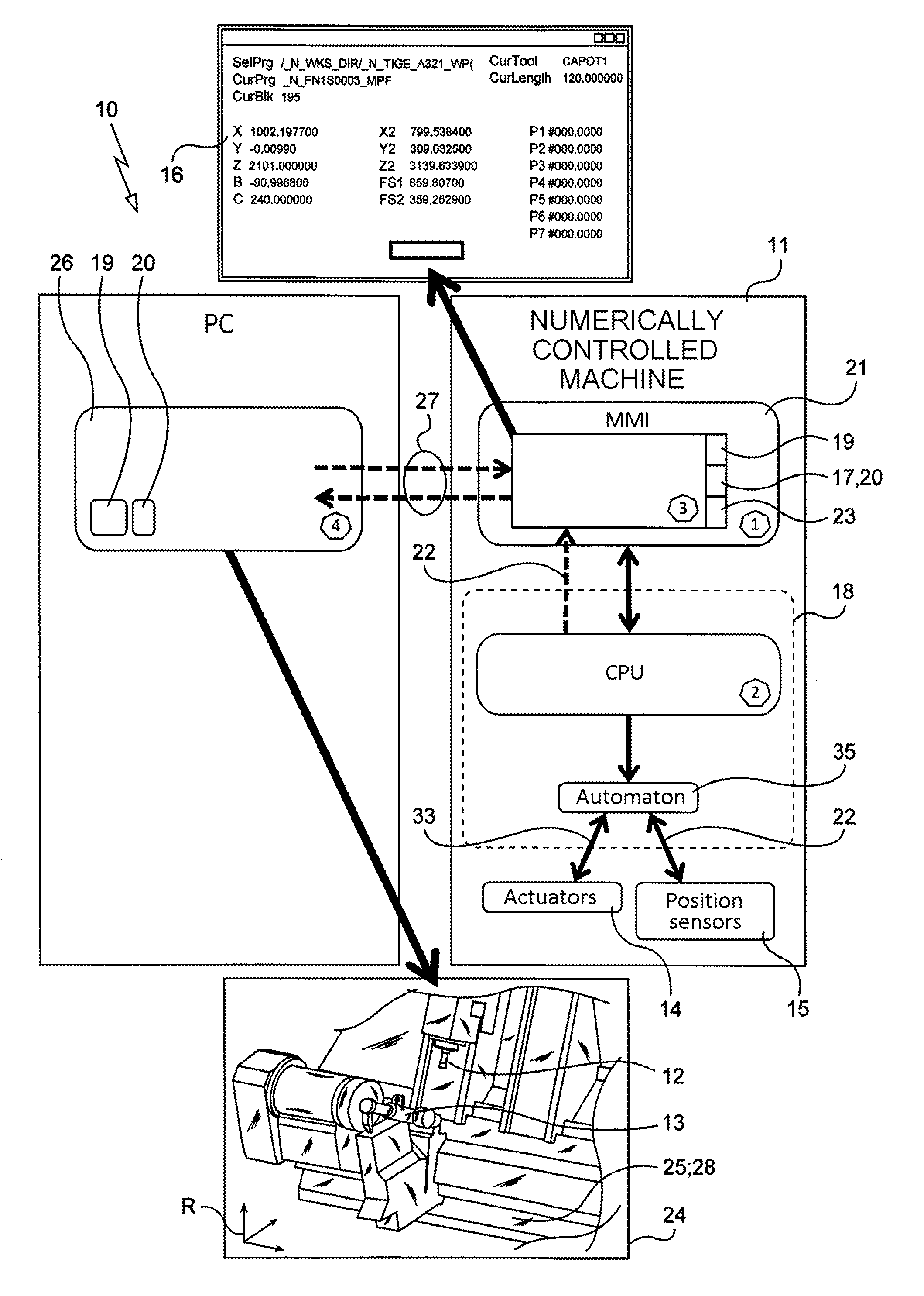
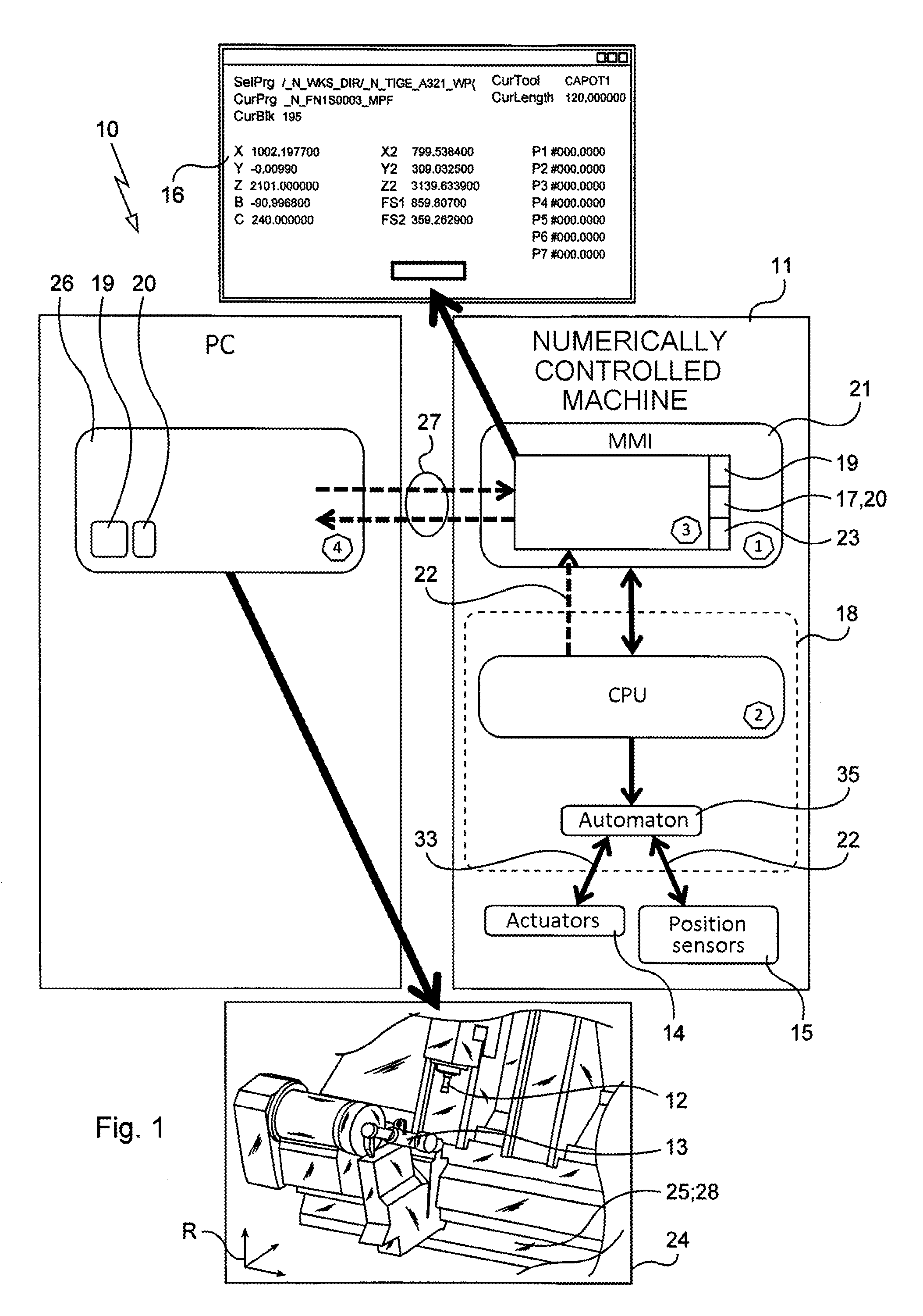
[0043]As mentioned above, it is sometimes difficult and / or impossible for the operator of a machining system to physically observe the real tool and the real blank during machining. Visibility of the real tool or of the real blank is often difficult because of the presence of protective systems, e.g. safety gates or casings placed between the real blank and the operator. During machining, visibility is also impeded by projected machining waste such as swarf or lubrication / cooling fluids.

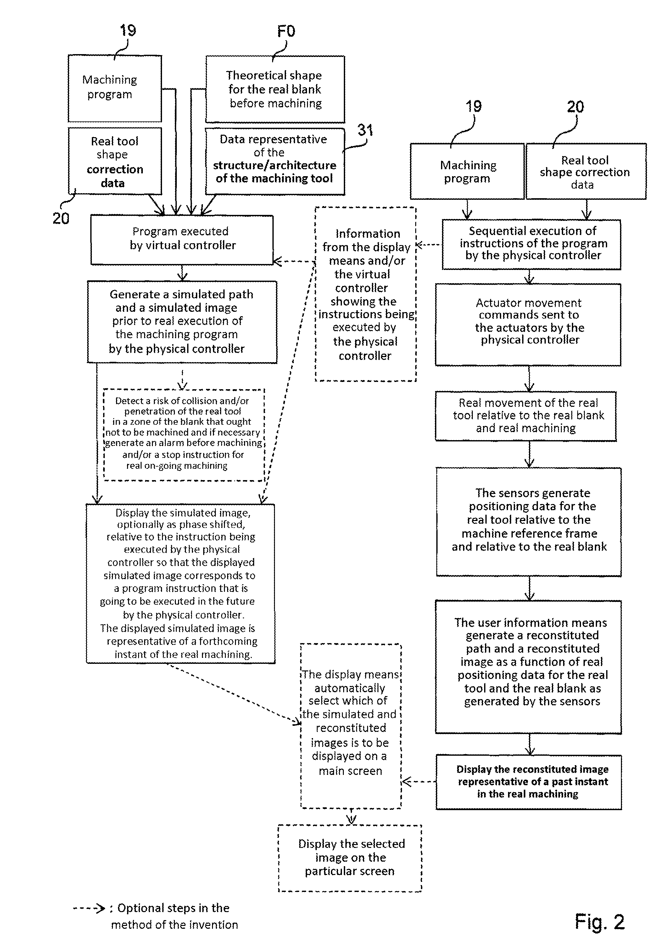
[0044]The machining system 10 in accordance with the invention as described below solves this problem by providing the user with images 25, 28 that are representative of the real machining, enabling the user to detect risks of a machining defect before they occur.

[0045]As explained below, these images 25, 28 are mainly:[0046]so-called “simulated” images 28 generated by simulation performed by a virtual controller 26 simulating the operation of the physical controller 18 that controls the real movemen...


PUM


Abstract

A machining system (10) comprising a machine comprising:
    • real tool (12);
    • actuators (14) for moving the real tool (12);
    • sensors (15) for generating positioning data (16) for the real tool (12);
    • a memory (17) for storing shape correction data (20) for the real tool (12); and
    • a physical controller (18) for executing a machining program (19) and for controlling the actuators (14) as a function of the shape correction data (20), so as to move the real tool (12) relative to the real blank (13).
On the basis of said data (22) representative of the positions of the real tool (12) and of the real blank (13), image display means (24) generate a reconstituted image (25) representative:
    • of the shape of the real blank (13); and
    • of the position of the real tool (12) at a given instant.

Description

BACKGROUND OF THE INVENTION[0001]The invention relates to the general field of machining systems comprising machining tools and control methods for such machining systems.[0002]Patent document EP 1 548 529 discloses a machining system comprising a machining tool comprising:[0003]at least one real tool for machining a real part;[0004]a plurality of actuators arranged to cause said at least one real tool to move relative to a real blank for machining in order to form the real part;[0005]a plurality of sensors for generating positioning data representative of a current position of the real tool relative to a real machine reference frame;[0006]a memory storing shape correction data for the real tool; and[0007]a physical controller arranged to execute a machining program and to control the actuators in compliance with instructions contained in the machining program and as a function of at least some of the shape correction data for the real tool, so as to move said at least one real tool...

Claims


Application Information

Patent Timeline
Patent Type & Authority Applications(United States)
IPC IPC(8): G05B19/27G05B19/414G05B19/4069G05B19/04G05B19/4063G05B19/402
CPCG05B19/27G05B19/4063G05B19/402G05B2219/39439G05B19/0415G05B19/4147G05B19/4069
Inventor CHEBROUX, CHRISTOPHELALLEMENT, DANIELCOMA, OLIVIERBELATON, OLIVIERGUENEAU, OLIVIER
Owner SAFRAN LANDING SYSTEMS
Why Eureka
Try Eureka