

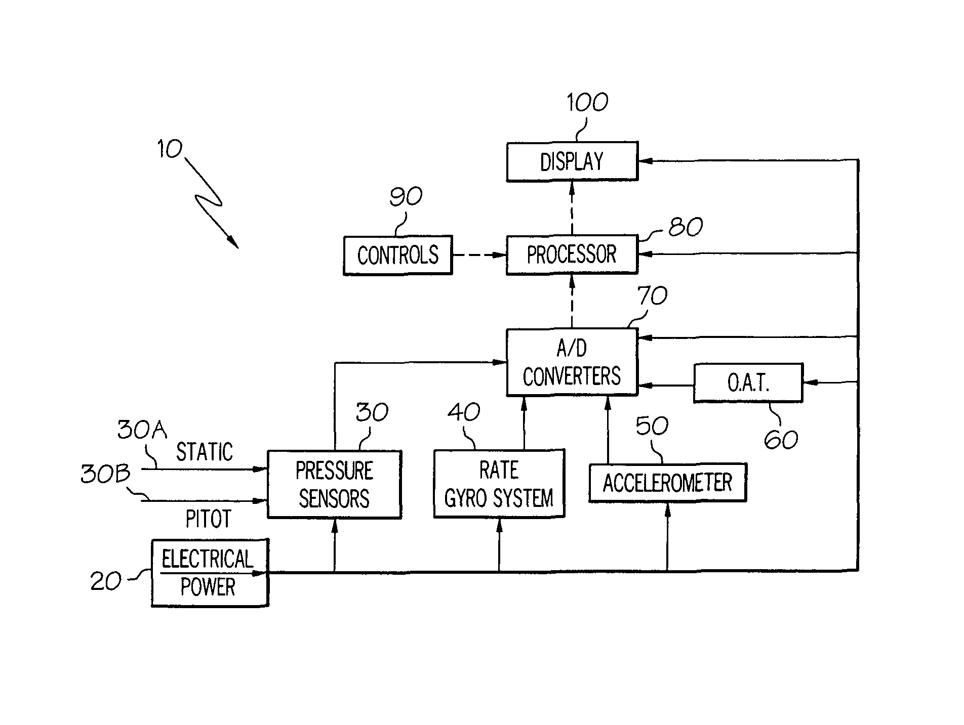
Low cost flight instrumentation system
a flight instrument and low cost technology, applied in the field of sensing and displaying aircraft operability conditions, can solve problems such as cognitive decline, failure of vacuum system or fault indicator, and failure of navigation system in general aviation aircraft, and achieve the effect of reducing cognitive declin
- Summary
- Abstract
- Description
- Claims
- Application Information
AI Technical Summary
Benefits of technology
Problems solved by technology
Method used
Image

Examples
Embodiment Construction
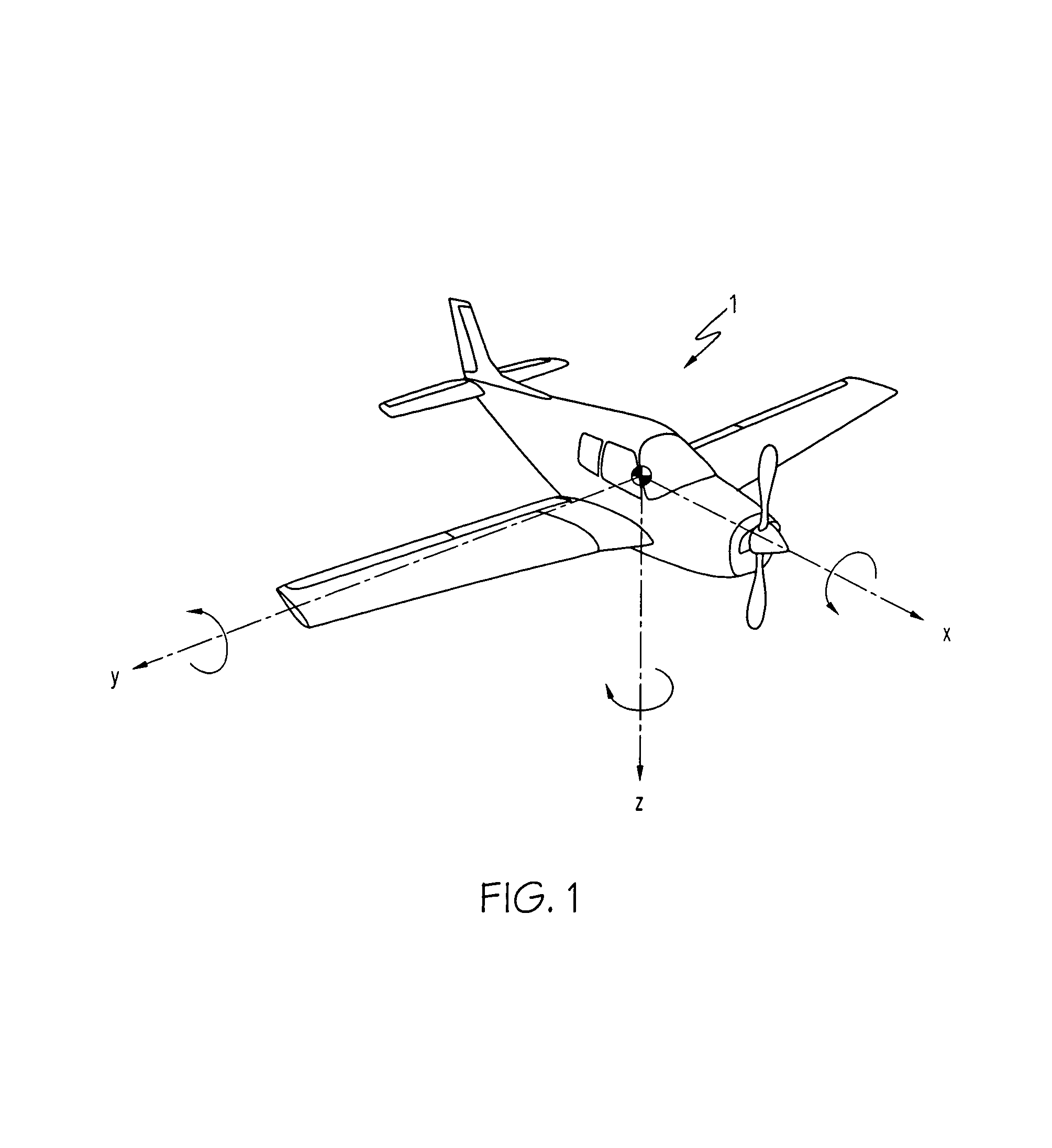
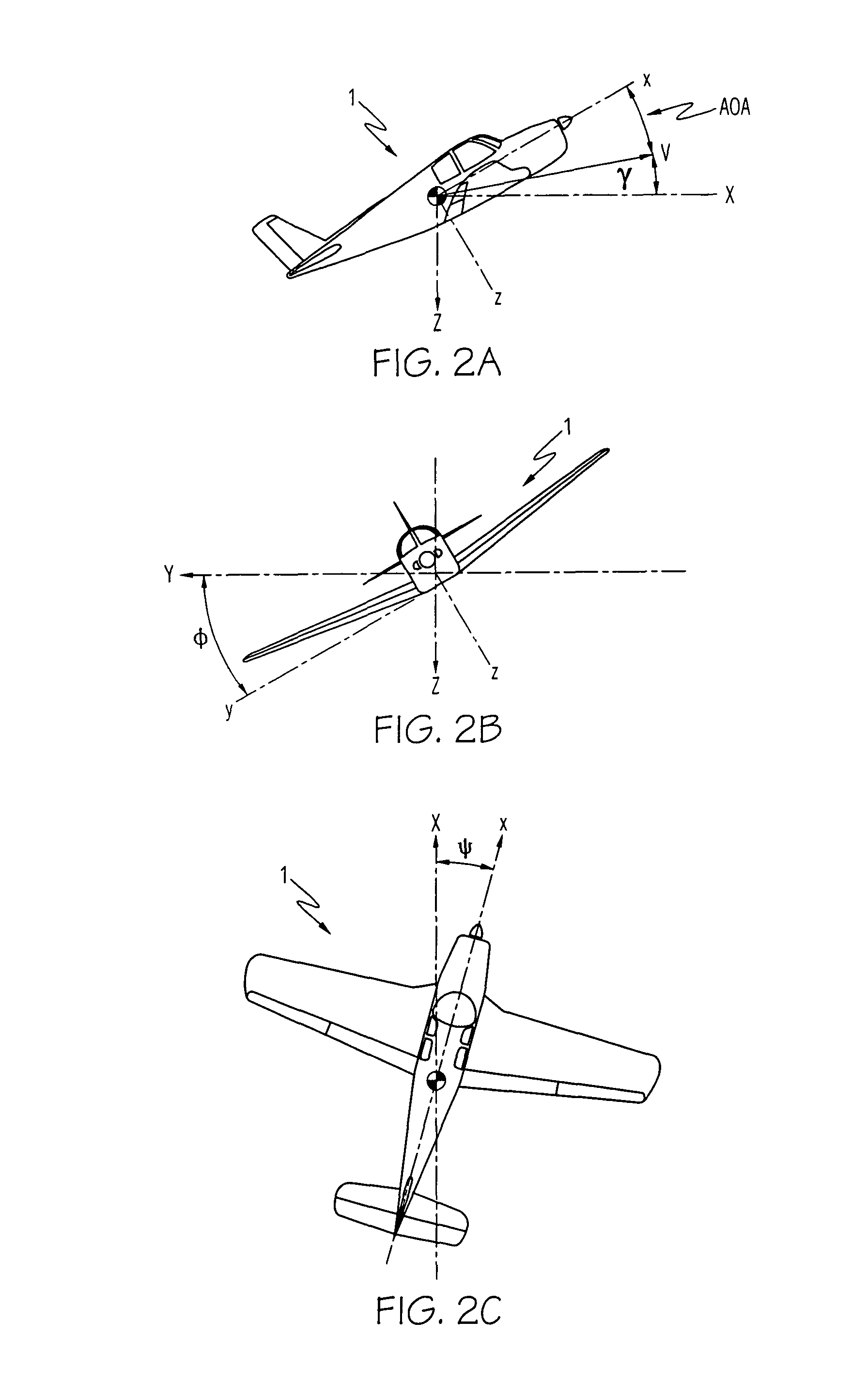
[0027]Referring initially to FIG. 1 and FIGS. 2A through 2C, a general aviation aircraft 1 is aligned along its three principal orthogonal aircraft body axes x, y and z is shown, where the three axes generally coincide with a Cartesian coordinate system with its vertex at the aircraft's center of gravity (CG). Referring with particularity to FIG. 2A through 2C, the aircraft's pitch, roll and yaw deviations from earth-referenced inertial axes are shown. In FIG. 2A, flight path angle is designated by angle γ (gamma), which is defined as the direction of travel (shown as velocity vector V) of aircraft 1 relative to the X (i.e., horizontal) inertial axis. Because of variations in aircraft weight, maneuver, and configuration, the pitch angle of aircraft 1 (the vertical angle between the x and X axes) can be significantly different than its flight path angle γ. AOA is defined as the angle between the velocity vector and the aircraft's longitudinal axis x, projected onto the aircraft's x-z...
PUM
 Abstract
Description
Claims
Application Information